56
NVA100X-D - Manual - 02 - 2016
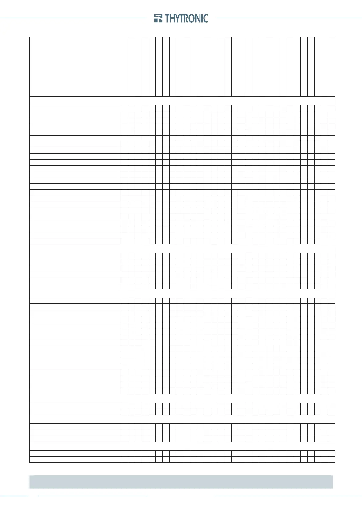
FUNCTION CHARACTERISTICS
Use of measured signals—
f
i
L1(L),
i
L2(L)
, i
L3(L)
I
L1(L),
I
L2(L)
, I
L3(L)
I
L1(H),
I
L2(H)
, I
L3(H)
I
L1-2nd,
I
L2-2nd,
I
L3-2nd
i
E1
, i
E2
I
E1
, I
E2
I
ECH
, I
ECL
I
1
I
2
u
L1,
u
L2
, u
L3
U
L1,
U
L2
, U
L3
U
12,
U
23
, U
31
u
E
U
E
U
1
U
2
U
EC
P, Q, S
E
Binary inputs I
N1-1...
I
N2-16
START Relays KC1-1...KC2-8
TRIP Relays KC1-1...KC2-8
START LEDs L1...L5,L1-1...L1-8
TRIP LEDs L1...L5,L1-1...L1-8
Selective block input BLIN1
Selective block output
Cold Load Pickup (CLP)
Second harmonic restraint
Logic block - BLOCK1
Selective block - BLOCK2
PROTECTIVE ELEMENTS
Underimpedance (21)
gg ggggg
Undervoltage (27)
gg gggg g
Positive sequence undervoltage (27V1)
gggggg
Directional active overpower (32P)
ggggg g
Undercurrent (37)
gggggg
Directional active underpower (37P)
ggggg g
Loss of field (40)
gg ggggg
Negative sequence overcurrent (46M-G)
g gggggg g
Thermal image (49MG)
g gg gggggggggg
Phase overcurrent (50/51)
g gggggggggg
Voltage restrained overcurrent (51V)
g g gggggg gg
Residual overcurrent (50N.1/51N.1, 50N.2/51N.2)
g gggggggggg
Residual overcurrent (50N/51NComp)
gg gggggggggg
Minimum power factor (55)
ggggg g
Overvoltage (59)
gg gggggg g
Residual overvoltage (59N)
g gggggg g
Negative sequence overvoltage (59V2)
g
Low impedance restricted earth fault (64REF)
g g gggggggggg
Directional earth fault overcurrent (67N)
g g g ggggggg gg
Directional earth fault overcurrent (67NComp)
ggggggggg
Under/overfrequency (81U/81O)
gggggg
Compensated differential (87G-87M-87T)
ggg gggg g
Breaker failure (BF)
g g ggggg g
CONTROL and MONITORING
Maximum number of startings (66)
gggggg
Automatic reclosure
ggggg
CT Monitoring (74CT)
g g
VT Monitoring(74VT)
ggggg g
Trip Circuit Supervision (TCS)
g
Second harmonic restraint (2NDH-REST)
g
MEASURES
Frequency
gg
Phase currents
gg
Measured residual current
g
Positive sequence current
g
Negative sequence current
g
Thermal image
g
Phase voltages
g
Phase-to-phase voltages
g
Residual voltage
g
Negative sequence voltage
g
Active power
g
Reactive power
g
Apparent power
g
Phase current /phase voltage displacement
gg
Power factor
gg
Reactive energy
g
EVENT RECORDER
Event 0
ggggg
Event ...299
ggggg
FAULT RECORDER
Fault 0
g g gg g g ggggg
Fault ...
g g gg g g ggggg
Fault 19
g g gg g g ggggg
OSCILLOGRAPHY
Record 1
ggg ggg ggg gg ggggg g
Record ...
ggg ggg ggg gg ggggg g
Note: the acquired measurements on the L side are used for all protective elements with the exception of differential (87) and phase overcurrent (50/51)
protections that also employ current measurements acquired on the H
 Loading...


