FUNCTION CHARACTERISTICS
177
NVA100X-D - Manual - 02 - 2016
Overvoltage - 59
Preface
Two operation thresholds, independently adjustable (U>, U>>) with adjustable delay (t
U
>, t
U
>>).
The fi rst one may be programmed with defi nite or inverse time, while the second threshold operates
with defi nite time characteristic.
Each threshold may be separately enabled or disabled.
The fi rst threshold trip (U>) may be inhibited by start of the second threshold (U>>).
Operation and settings
The fundamental frequency of a selectable voltages, phase to ground (U
L1
, U
L2
, U
L3
) or phase-to-
phase voltages (U
12
, U
23
, U
31
) are employed:
Each of three voltages is compared with the setting values (U>, U>>). The start and trip logic may
be selected OR or AND.
With OR selection, a start is issued when at least one of the three voltages overcomes the adjust-
able threshold (START); after expiry of the associated operate time (t
U
>, t
U
>>) a trip command is
issued; if instead the voltages drops below the threshold, the element is restored.
With AND selection, a start is issued when all the three voltages overcomes the adjustable thresh-
old; after expiry of the associated operate time (t
U
>, t
U
>>) a trip command is issued; if instead the
voltage drops below the threshold, the element is restored.
The fi rst threshold (U>) may be programmed with defi nite or inverse time according the following
characteristic curve:
t=0.5 t
U
>
inv
/ [(U/U>
inv
) - 1]
Where:
t: operate time
U>
inv
: threshold setting
t
U>inv
: operate time setting
For the inverse time characteristic, following data applies:
The operate time setting is referred to an input voltage equal to 1.5 of the pickup value.
Asymptotic reference value (minimum pickup value): 1.1 U>
inv
Minimum operate time: 0.1 s
Range where the equation is valid: 1.1 ≤ U/U>
inv
≤ 4
If U>
inv
pickup ≥ 0.5 U
n
, the upper limit is 2 U
n
.
The fi rst overvoltage element can be programmed with defi nite or inverse time characteristic by
setting the U>Curve parameter (DEFINITE, INVERSE) available inside the Set \ Profi le A(or B) \
Overvoltage-59 \ U> Element \ Setpoints menu.
Each element can be enabled or disabled by setting ON or OFF the U> Enable parameter inside
the Set \ Profi le A(or B) \ Overvoltage-59 \ U> Element \ Setpoints menu and/or the State parameter
inside the Set\Profi le A(or B) \ Overvoltage-59 \ U>> Element \ Defi nite time.
The voltage measurement type (Phase-to-phase or phase-to-neutral) and the operating logic (AND
or OR), is adjustable inside the Set \ Profi le A(or B) \ Overvoltage-59 \ Common confi guration menu
by means the Utype59 parameter; the allowed setting are Uph-ph (phase-to-phase) or Uph-n
(phase-to-neutral).
The corresponding unit are p.u. U
n
for Uph-ph setting and p.u. E
n
for Uph-n setting.
—
•
•
•
•
•
U
12
=|U
L1
-U
L2
|
U
23
=|U
L2
-U
L3
|
U
31
=|U
L2
-U
L1
|
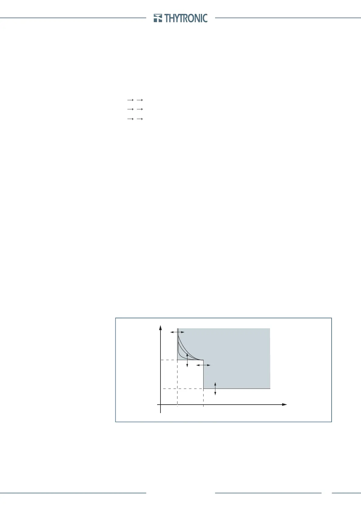
t-int-F59.ai
U
U>>
t
U
>
t
U
>>
U>
t
General operation time characteristic for the overvoltage elements - 59
TRIP
 Loading...


