FUNCTION CHARACTERISTICS
117
NVA100X-D - Manual - 02 - 2016
Phase rotation direction check - 47
Preface
The starting of synchronous motors is inhibited when the 47 function becomes active.
The element can be enabled or disabled.
Operation and settings
The positive sequence voltage is computed as:
U
1
=(U
L1
+e
+j120°
·U
L2
+e
-j120°
·U
L3
)/3
with e
-j120°
=-1/2-j√3/2, e
j120°
=-1/2+j√3/2.
The positive sequence voltage is compared with the setting threshold (U
s1
<); voltages lower than
the associated pickup value are detected and a start is issued if all the phase-to-phase voltages are
larger than an adjustable threshold (U
s
>).
The element can be enabled or disabled by setting ON or OFF the 47Enable parameter inside the
Set \ Profi le A(or B) \ Phase rotation direction check 47 \ 47 Element \ Setpoints menu.
Logical block (Block1)
If the 47BLK1 enabling parameter is set to ON and a binary input is designed for logical block
(Block1), the element is blocked off whenever the given input is active.
[1]
The enabling parameter is available inside the Set \ Profi le A(or B) \ Phase rotation direction check
47 \ 47 Element \ Setpoints menu, while the Block1 function must be assigned to the selected binary
input inside the Set \ Board1(2) inputs \ Binary input IN1-1...INx-x menu.
Note 1 The exhaustive treatment of the logical block (Block 1) function may be found in the “Logic Block” paragraph inside CONTROL AND MONITOR-
ING section
—
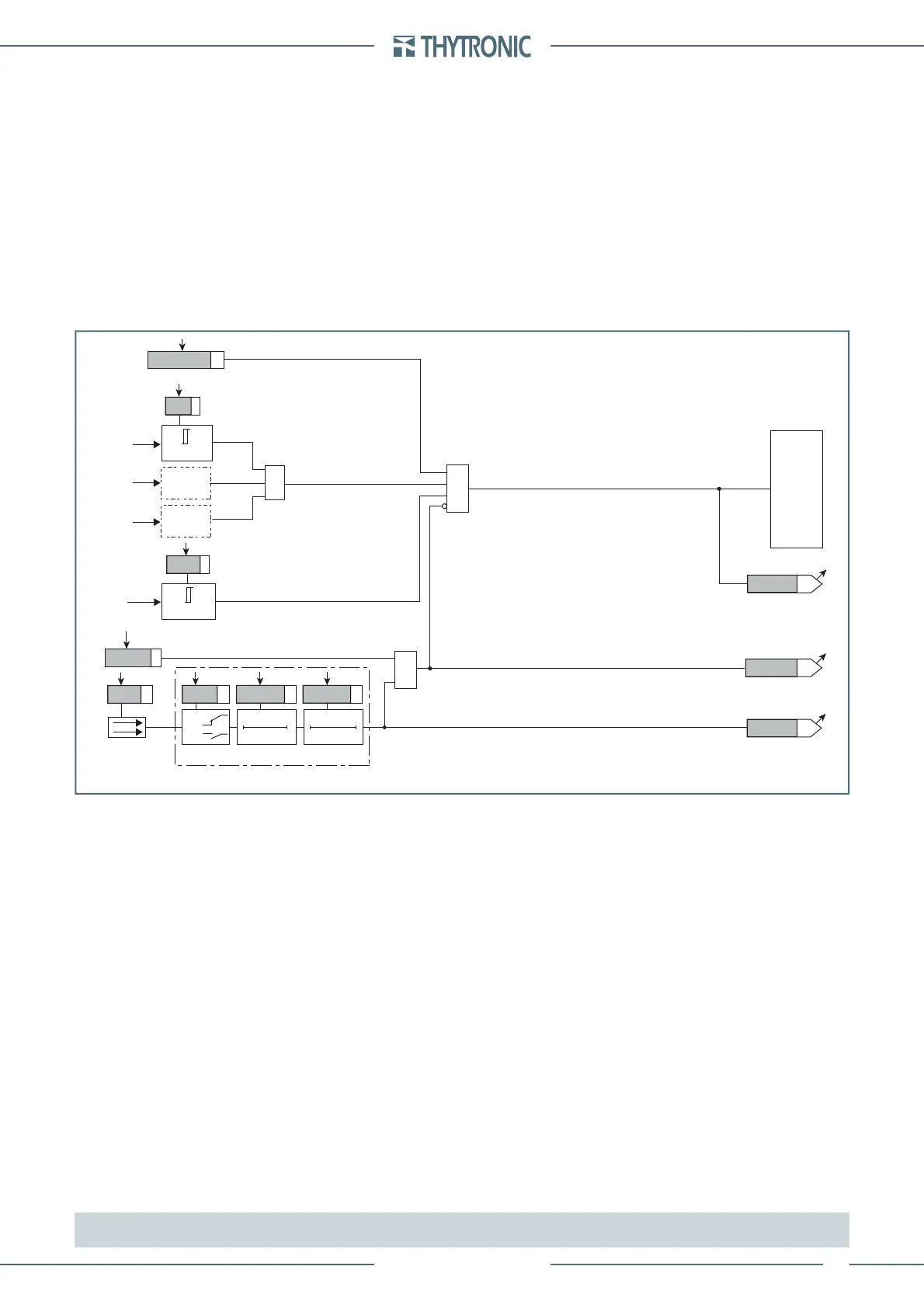
Fun-F47_S1.ai
Phase rotation direction check - 47
TRIPPING MATRIX
(LED+RELAYS)
47TR-K
47TR-L
Trip 47
BLK147
&
Enable (ON≡Enable)
47BLK1
Block1
Block1
U
1
Binary input INx
T0
Logic
INx
t
ON
INx
t
ON
INx
t
OFF
T0
n.o.
n.c.
INx
t
OFF
U
1
≤
U
S1
<
&
&
U
12
U
23
U
31
U
12
≥
U
S
>
U
S
>
ON≡Enable 47 element
47 Enable
U
S1
<
 Loading...


