40
NVA100X-D - Manual - 02 - 2016
TECHNICAL DATA
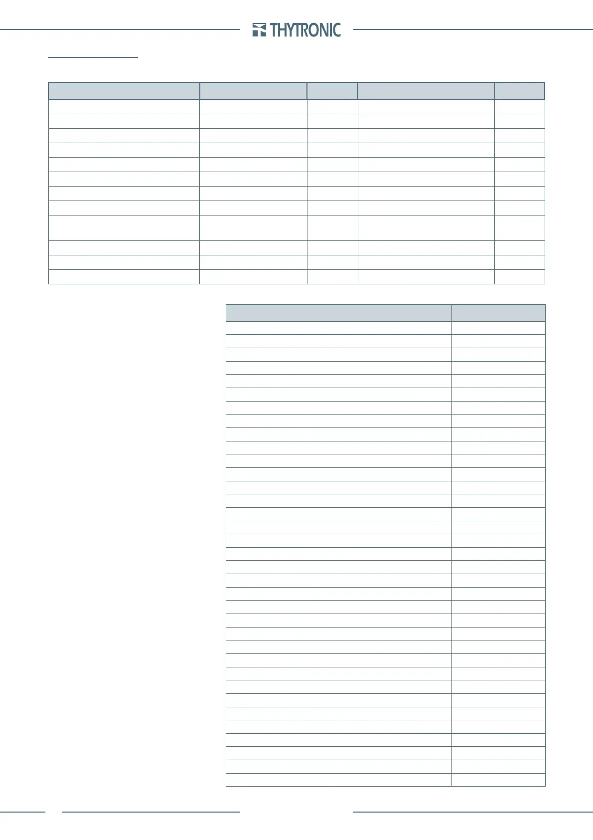
3.9 METERING
Accuracy (type test)
MEASURE Reference values
Accuracy
Reference values
Accuracy
Phase current 0.1 I
n
0.2% 1 I
n
0.03%
Measured residual current 0.01 I
En
0.3% 1 I
En
0.02%
Calculated residual current 0.1...1 I
n
2% 1 I
n
0.3%
Phase voltage 0.1 U
n
0.2% 1 U
n
0.03%
Measured residual voltage 0.01 U
En
0.02% 0.1 U
En
0.02%
Calculated residual voltage 0.01 U
ECn
0.5% 0.1 U
ECn
0.3%
Power - Energy 0.01 P
n
2% 0.1...1 Pn 0.3%
Frequency 0.02 U
n
3 mHz 1 U
n
2 mHz
Phase 0.002 I
En
- 0.004 U
En
1.5°
0.005 I
En
- 0.01 U
En
0.1 I
En
- 0.5 U
En
0.2°
Positive/Negative sequence current I
1
or I
2
= 0.5 I
n
0.5% I
1
or I
2
= 1 I
n
0.5%
Positive/Negative sequence voltage 0.01 U
n
4% 0.15 U
n
0.3%
Pickup and operate time 1.5 x setting for fist element 5% ± 10 ms 2.5 x setting for other elements 5% ± 10 ms
Measures
Measure Symbol
Locked frequency f
l
U
12
frequency f
U12
U
23
frequency f
U23
U
31
frequency f
U31
RMS value of fundamental comp. for phase currents side H I
L1H
, I
L2H
, I
L3H
RMS value of fundamental comp. for phase currents side L I
L1L
, I
L2L
, I
L3L
RMS value of phase currents side L I
L1L...3Lrms
RMS value of fundamental component for phase voltages U
L1
, U
L2
, U
L3
RMS value of fundamental com. for residual current side 1 I
E1
RMS value of fundamental com. for residual current side 2 I
E2
RMS value of fundamental com. for residual voltage U
E
Compensated currents side H I
L1cH
, I
L2cH
, I
L3cH
Compensated currents sid L I
L1cL
, I
L2cL
, I
L3cL
Stabilization currents I
SL1
, I
SL2
, I
SL3
Differential currents I
DL1
, I
DL2
, I
DL3
Second harmonic of differential currents I
DL1-2nd
, I
DL2-2nd
, I
DL3-2nd
Fifth harmonic of differential currents I
DL1-5th
, I
DL2-5th
, I
DL3-5th
Thermal image DTheta
Phase-to-phase voltages U
12
, U
23
, U
31
Calculated residual voltage U
EC
Calculated residual current side H and side L I
ECH
, I
ECL
Maximum current between I
L1
-I
L2
-I
L3
I
Lmax
Maximum RMS current between I
L1
-I
L2
-I
L3
I
Lmax-rms
Minimum current between I
L1
-I
L2
-I
L3
I
Lmin
Minimum RMS current between I
L1
-I
L2
-I
L3
I
Lmin-rms
Average current between I
L1
-I
L2
-I
L3
I
LL
Average RMS current between I
L1
-I
L2
-I
L3
I
L-rms
Average voltage between U
L1
-U
L2
-U
L3
U
L
Maximum voltage between U
L1
-U
L2
-U
L3
U
Lmax
Minimum voltage between U
L1
-U
L2
-U
L3
U
Lmin
Average voltage between U
12
-U
23
-U
31
U
Maximum voltage between U
12
-U
23
-U
31
U
max
Minimum voltage between U
12
-U
23
-U
31
U
min
Displacement angle of I
L1
respect to U
L1
Phi
L1
Displacement angle of I
L2
respect to U
L2
Phi
L2
—
—
 Loading...


