110
NVA100X-D - Manual - 02 - 2016
FUNCTION CHARACTERISTICS
Negative sequence overcurrent for motor protection - 46M
Preface
The motor may operate with an unbalanced load due to single-phase or non-linear loads, the trip-
ping of fuses, line interruption in one phase, asymmetric faults, tripping and unipolar reclosing on the
transmission lines.
The unbalanced load creates a stator magnetic fi eld rotating contrariwise to the direction of rotation,
which hence corresponds to a magnetic fi eld rotating at twice the speed with respect to the rotor.
Hence, currents are induced at twice the frequency in the rotor magnetic circuit (parasitic currents),
the fi eld windings and the damper windings, responsible for increased loss of iron and copper and
hence overheating of the machine.
The unbalanced load protective device estimates the inverse sequence current I
2
from the
phase current readings on side L; two operation thresholds, independently adjustable (I
2
>,
I
2
>>) with adjustable delay (t
2
>, t
2
>>) are available.
The fi rst one may be programmed with defi nite or inverse time according the IEC and ANSI/IEEE
standard, as well as with I
2
t or EM curve.
The second threshold has a defi nite time characteristic.
For each threshold a reset time can be set (t
2>RES
, t
2>>RES
) useful to reduce the clearing time for
intermittent faults.
The fi rst threshold trip may be inhibited by start of the second threshold (I
2
>>).
Operation and settings
The negative sequence current is computed as:
I
2
=(I
L1L
+e-
j120°
·I
L2L
+e
+j120°
·I
L3L
)/3
where e
-j120°
=-1/2-j√3/2, e
j120°
=-1/2+j√3/2.
The negative sequence current is compared with the setting values. Currents above the associated
pickup value are detected and a start is issued. After expiry of the associated operate time (t
2
>, t
2
>>)
a trip command is issued; if instead the current drops below the threshold, the element is restored.
The fi rst threshold (I
2
>) may be programmed with defi nite or inverse time according the following
characteristic curves:
Standard Inverse Time (IEC 255-3/BS142 type A or SIT): t = 0.14 · t
2
>
inv
/ [(I
2
/I
2
>
inv
)
0.02
- 1
Very Inverse Time (IEC 255-3/BS142 type B or VIT): t = 13.5 · t
2
>
inv
/ [(I
2
/I
2
>
inv
) - 1]
Extremely Inverse Time (IEC 255-3/BS142 type C or EIT): t = 80 · t
2
>
inv
/ [(I
2
/I
2
>
inv
)
2
- 1]
Moderately Inverse (ANSI/IEEE type MI): t = t
2
>
inv
· {0.01 / [(I
2
/I
2
>
inv
)
0.02
- 1] + 0.023}
Very Inverse (ANSI/IEEE type VI): t = t
2
>
inv
· {3.922 / [(I
2
/I
2
>
inv
)
2
- 1] + 0.098}
Extremely Inverse (ANSI/IEEE type EI): t = t
2
>
inv
· {5.64 / [(I
2
/I
2
>
inv
)
2
- 1] + 0.024}
I-squared-t (I
2
t = K): t = 16 · t
2
>
inv
/ (I
2
/I
2
>
inv
)
2
Electromechanical (EM): t = t
2
>
inv
· {0.28 / [-0236 · (I
2
/I
2
>
inv
)
-1
+ 0.339]}
Where:
t: operate time
I
2
>
inv
: threshold setting
t
2
>
inv
: operate time setting
The second threshold has a defi nite time characteristic.
For all inverse time characteristics, following data applies:
Asymptotic reference value (minimum pickup value): 1.1 I
2
>
inv
Minimum operate time: 0.1 s
Range where the equation is valid:
[1]
1.1 ≤ I
2
/I
2
>
inv
≤ 20
For all defi nite time elements the upper limit for measuring is 50 I
n
.
All overcurrent elements can be enabled or disabled by setting ON or OFF the I2> Enable and/or
I2>> Enable parameters inside the Set \ Profi le A(or B) \ Negative sequence overcurrent - 46 \
I2> Element (I2>> Element) \ Setpoints menus.
Note 1 When the input value is more than 20 times the set point , the operate time is limited to the value corresponding to 20 times the set point
—
•
•
•
•
•
•
•
•
•
•
•
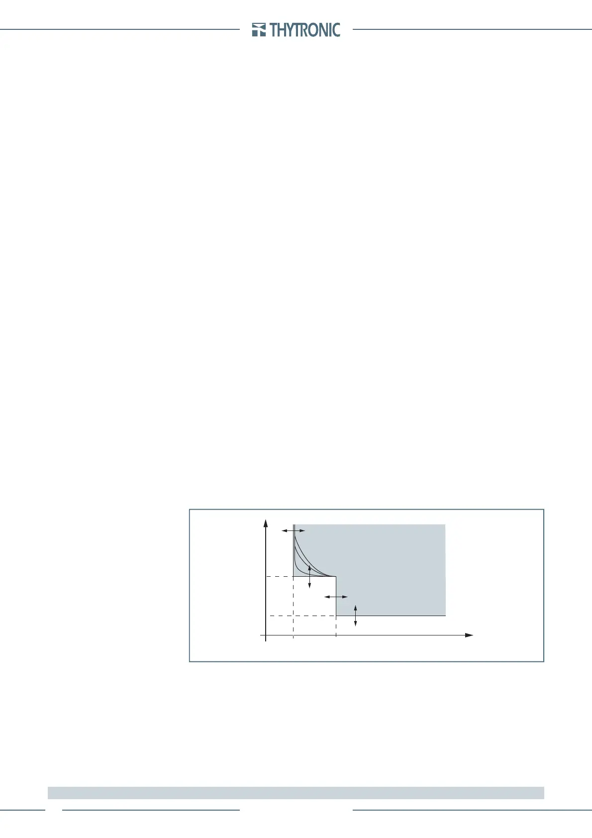
General operation time characteristic curve for the negative sequence overcurrent element - 46M
t-int-F46.ai
I
2
I
2
>>
t
2
>
t
2
>>
I
2
>
t
TRIP
 Loading...


