FUNCTION CHARACTERISTICS
111
NVA100X-D - Manual - 02 - 2016
The fi rst overcurrent element can be programmed with defi nite or inverse time characteristic by
setting the I2>Curve parameter (DEFINITE, IEC/BS A, IEC/BS B, IEC/BS C, ANSI/IEE MI,
ANSI/IEE VI, ANSI/IEE EI, I2t, EM) available inside the Set \ Profi le A(or B) \ Negative sequence
overcurrent - 46 \ I2> Element \ Setpoints menu.
The trip of I2> element may be inhibited by the start of the second element (I2>>) by set-
ting ON the Disable I2> by start I2>> (I2>disbyI2>>) parameter available inside the
Set \ Profi le A(or B) \ Negative sequence overcurrent-46 \ I2>> Element \ Setpoints menu.
All the parameters can be set separately for Profi le A and Profi le B (Set \ Profi le
A(or B) \ Negative sequence overcurrent - 46 \ I2> Element (I2>> Element) \ Setpoints menus).
An adjustable reset time delay is provided for every threshold (t
2
>
RES
, t
2
>>
RES
).
Each element can produce the Breaker Failure output if the I2> BF and/or I2>> BF parameters
are set to ON. The parameters are available inside the Set \ Profi le A(or B) \ negative sequence
overcurrent - 46 \ I2> Element (I2>> Element) \ Setpoints menus.
[1]
Note 1 The common settings concerning the Breaker failure protection are adjustable inside the Breaker Failure - BF menu.
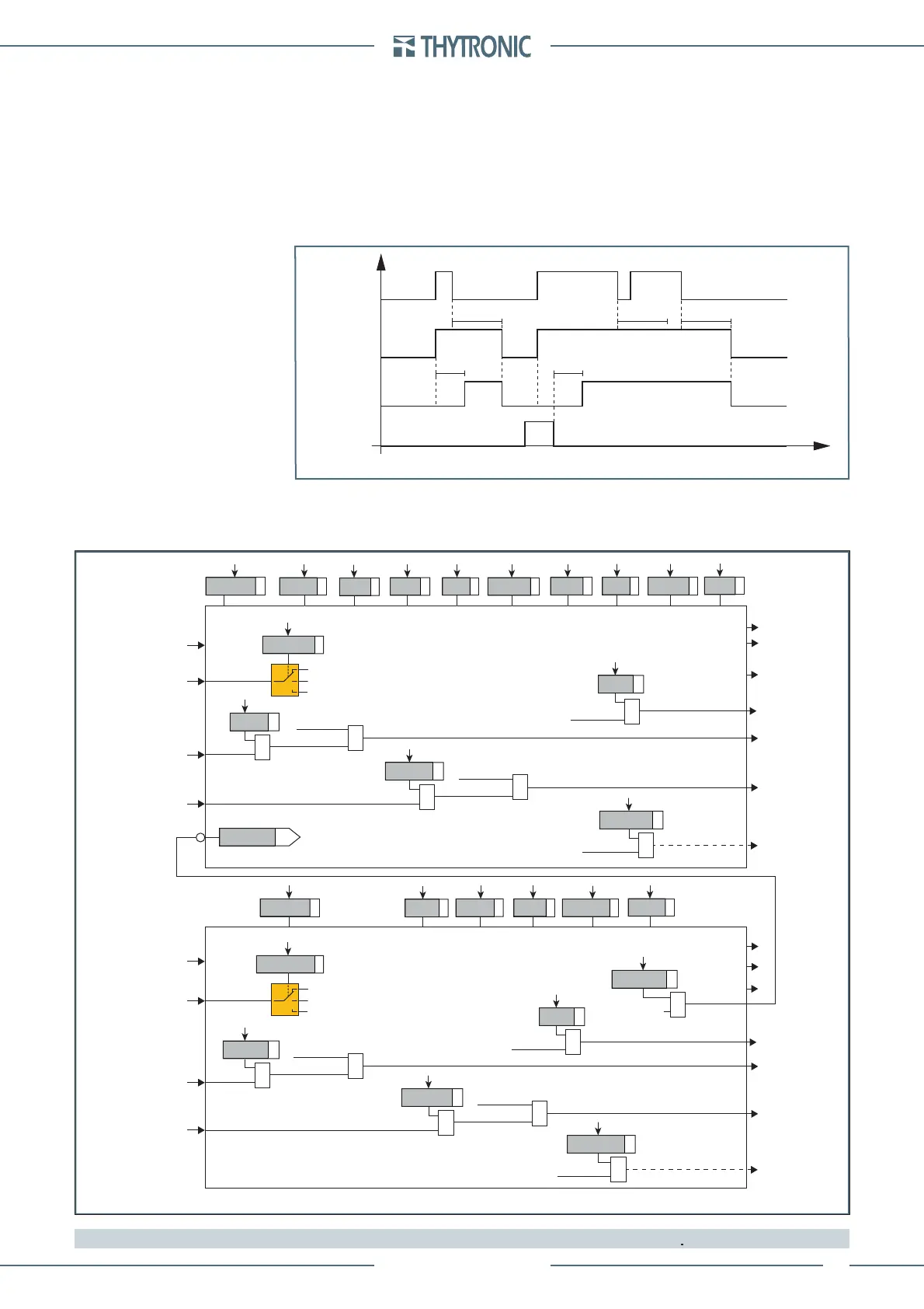
Timers-F46M.ai
I2> Start
I2> Trip
t
2
> t
2
>
RESET
INPUT
t
2
>
RES
t
2
>
RES
t
2
>
RES
t
I2> element timers - 46M
all-F46M.ai
I
2
BLK1I2>>
I2>> Element
BLK2OUT
Start I2>>
Start I2>>
Trip I2>>
&
I2> disbyI>>
&
I2>>BLK1
&
I2>>BLK2IN
t2
>>
def
I2CLP>>
def
I2>>
def
t2CLP>>
t2
>>
RES
I2>> Enable
I2> inhibition
Block1
BLK1I2>
CLPI2>
CLPI2>>
I
2
I2> Element
BLK2OUT
BLK2INI2>
BLK2INI>>
Start I2>
Trip I2>
&
I2>BLK1
Block2
&
I2>BLK2IN
I2>BLK2OUT
I2>>BF
I2>> Trip
&
I2>>BF
I2>BF
Trip I2>
&
I2>BF
Start I2>
&
I2>>BLK2OUT
Start I2>>
&
Block1
Block2
t2>
def
I2CLP>
def
I2>
def
t2>
inv
I2CLP>
inv
I2>
inv
I2>Curve
t2CLP>
t2>
RES
I2> Enable
Start I2>
&
Start I2>>
&
Start I2>>
&
Start I2>
&
General logic diagram of the negative sequence overcurrent elements - 46M
I2CLP>Mode
Starting control set
Change setting
Element blocking
OFF
I2CLP>>Mode
Starting control set
Change setting
Element blocking
OFF
 Loading...


