182
NVA100X-D - Manual - 02 - 2016
FUNCTION CHARACTERISTICS
TV monitoring (74VT)
For both measuring criteria, a block of the U
E
> and U
E
>> threshold may be select when the 74VT
function is active (internal and/or external). The blocking enabling parameters 74VTint59N and-
74VText59N are available inside the Set \ Profi le A(or B) \ Residual overvoltage-59N \ Common
confi guration menu.
[1]
The fi rst threshold trip (U
E
>) may be inhibited by start of the second threshold (U
E
>>) by setting ON
the UE> Disabling by UE>> start (UE>disbyUE>>) parameter available inside the Set \ Profi le A(or
B) \ Residual overvoltage-59N \ UE>> Element \ Setpoints menu.
An adjustable reset time delay is provided for every threshold (t
UE>RES
, t
UE>>RES
).
Breaker failure (BF)
Both residual overvoltage elements (U
E
>, U
E
>>) can produce the Breaker Failure output if the
UE>BF and UE>>BF parameters are set to ON.
The parameters are available inside the Set \ Profi le A(or B) \ Residual overvoltage - 59N \ UE> Element
(UE>> Element) \ Setpoints menus.
[2]
Logical block (Block1)
If the UE>BLK1 and/or UE>>BLK1 enabling parameters are set to ON and a binary input is de-
signed for logical block (Block1), the protection is blocked off whenever the given input is active.
The trip timer is held in reset condition, so the operate time counting starts when the input block goes
down.
[3]
The enabling parameters are available inside the Set \ Profi le A(or B) \ Residual overvoltage
- 59N \ UE> Element (UE>> Element) \ Setpoints menus, while the Block1 function must be assigned
to the selected binary input inside the Set \ Board1(2) inputs \ Binary input IN1-1...INx-x) menus.
All the parameters can be set separately for Profi le A and Profi le B.
Note 1 The operating time must be adjusted to a greater value than the 74VT activation time (internal or binary input)
Note 2 The common settings concerning the Breaker failure protection are adjustable inside the Breaker Failure - BF menu.
Note 3 The exhaustive treatment of the logical block (Block 1) function may be found in the “Logic Block” paragraph inside CONTROL AND MONITOR-
ING section.
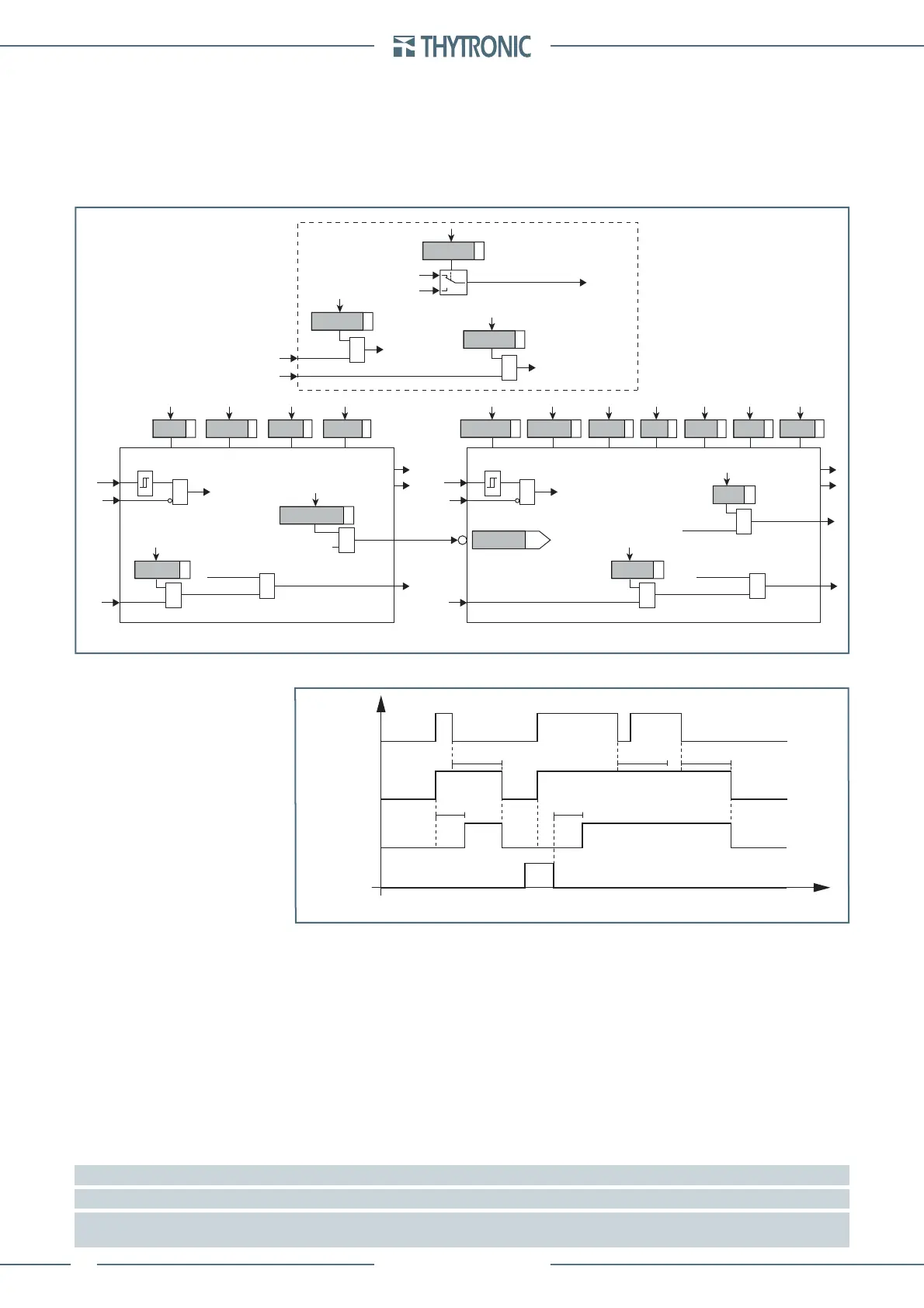
all-F59N.ai
Logic diagram concerning the residual overvoltage element - 59N
U
E
UE> Element
UE>> Element
Start U>>
Start UE>> Start UE>
Trip UE>Trip UE>>
&
UE> disbyUE>>
U> inhibition
t
UE>
def
t
UE>
inv
UE>
def
t
UE>>
def
t
UE>>RES
t
UE>RES
UE>>
def
UE>
inv
UE> CurveUE> EnableState
Block1
BLK1UE>
&
UE>BLK1
Start UE>
&
Block1
BLK1UE>>
&
UE>>BLK1
Start UE>>
&
UE>BF
Trip UE>
&
UE>BF
&
74VT
U
E
&
74VT
&
74VTint
74VTint-Block
74VText-Block
&
74VText
U
E
(misura diretta)
U
EC
(misura calcolata)
U
E
Common configuration
3Votype59 N
74VTint59 N
74VText59 N
Timers-F59N.ai
UE> Start
UE> Trip
t
UE>
t
UE>
RESET
INPUT
t
UE>RES
t
UE>RES
t
UE>RES
t
Timers concerning the first element of residual overvoltage protection- 59N
 Loading...


