164
NVA100X-D - Manual - 02 - 2016
FUNCTION CHARACTERISTICS
setting ON the Disable IE(H)>> by start IE(H)>>> (IE(H)>>disbyIE(H)>>>) parameter available
inside the Set \ Profi le A(or B) \ Calculated residual overcurrent-50N(Comp)/51N(Comp) side H \
IE(H)>>> Element \ Setpoints menus for side H element, the IE(L)>>disbyIE(L)>>> parameter
available inside the Set \ Profi le A(or B) \ Calculated residual overcurrent-50N(Comp)/51N(Comp)
side L \ IE(L)>>> Element \ Setpoints menus for side L element and the IE(T)>>disbyIE(T)>>>
parameter available inside the Set \ Profi le A(or B) \ Calculated residual overcurrent-50N(Comp)/
51N(Comp) side T \ IE(T)>>> Element \ Setpoints menus for side T element.
All the parameters can be set separately for Profi le A and Profi le B
E’ regolabile un tempo di ripristino costante per ciascuna delle soglie (t
E(H)
>
RES
, t
E(H)
>>
RES
,
t
E(H)
>>>
RES
per il lato H e t
E(L)
>
RES
, t
E(L)
>>
RES
, t
E(L)
>>>
RES
per il lato L).
Breaker failure (BF)
Each calculated residual overcurrent element can produce the Breaker Failure output if the IEC>
BF, IEC>> BF e IEC>>> BF. are set to ON. The parameters are available inside the Set \ Profi le
A(or B) \ Calculated residual overcurrent-50N(Comp)/51N(Comp) \ IEC> Element (IEC>> Element,
IEC>>> Element) \ Setpoints menus.
[1]
Second harmonic restraint
For all elements, a block from the second harmonic restraint may be set by setting ON the IEC>2ndh-
REST, IEC>>2ndh-REST, IEC>>>2ndh-REST.
The parameters are available inside the Set \ Profi le A(or B) \ Residual overcurrent-50N(Comp)/
51N(Comp) \ IEC> Element (IEC>> Element, IEC>>> Element) \ Setpoints menus.
Cold load pickup (CLP)
If the CLP function (Cold Load Pick-up) is enabled for element blocking, the element may be blocked
for an adjustable time interval, starting from circuit breaker closure.
If the CLP function (Cold Load Pick-up) is enabled for setting change, the selected threshold may be
changed for an adjustable time interval, starting from the circuit breaker closure.
The operating mode may be select by setting ON-Element blocking or ON-Change setting the
IECCLP> Mode, IECCLP>> Mode, IECCLP>>> Mode parameter.
The operating modes and the CLP Activation time parameters (tECCLP>, tECCLP>> e tEC-
CLP>>>) may be adjusted inside the Set \ Profi le A(or B) \ Residual overcurrent-50N(Comp)/
51N(Comp) \ IEC> Element (IEC>> Element, IEC>>> Element) \ Setpoints menus.
The threshold inside CLP (IECCLP>def, IECCLP>inv,....) can be set inside the Set \ Profi le A(or B)
\ Residual overcurrent-50N(Comp)/51N(Comp) \ IEC> Element (IEC>> Element, IEC>>> Element) \ Def-
inite time (Inverse time) menus.
For every of the four thresholds the following block criteria are available:
Logical block (Block1)
If the IEC>BLK1, IEC>>BLK1 and/or IEC>>>BLK1 enabling parameters are set to ON and a
binary input is designed for logical block (Block1), the concerning element is blocked off whenever
the given input is active.
[2]
The enabling parameters are available inside the Set \ Profi le A(or B) \
Residual overcurrent-50N(Comp)/51N(Comp) \ IEC> Element (IEC>> Element, IEC>>> Element) \ Set-
points menus, while the Block1 function must be assigned to the selected binary input inside the
Set \ Board1(2) inputs \ Binary input IN1-1...INx-x) menus .
Selective block (Block2)
All along the protective elements the selective block may be set.
The logic selectivity function may be performed by means any combination of the following I/O:
One committed pilot wire input (BLIN1).
One or more binary inputs designed for input selective block.
One committed pilot wire output (BLOUT1).
Note 1 The common settings concerning the Breaker failure protection are adjustable inside the Breaker Failure - BF menu.
Note 2 The description of the logical block (Block 1) function may be found in the “Logic Block” paragraph inside CONTROL AND MONITORING section
•
•
•
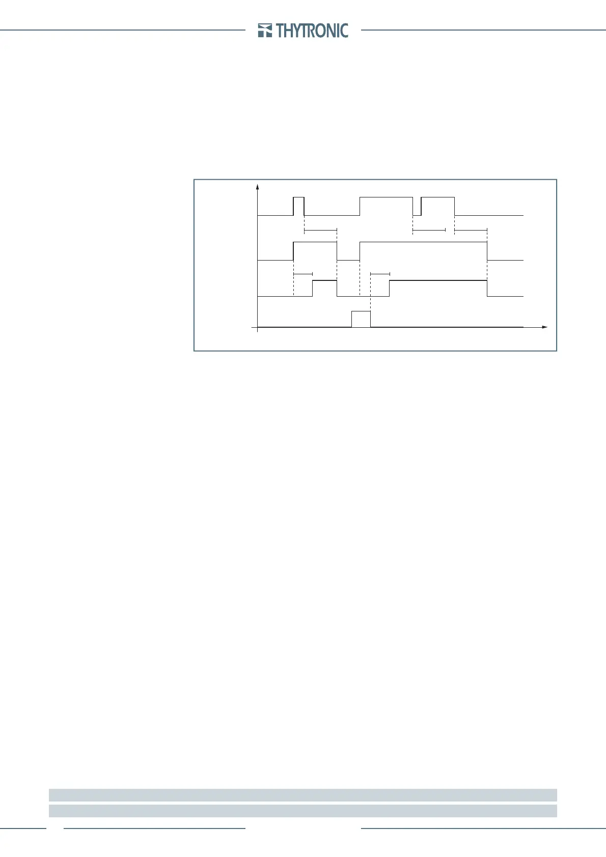
IEC> element residual overcurrent 50N(Calc)/51N(Calc) - Timers
IEC> Start
IEC> Trip
RESET
INPUT
t
EC
t
EC
t
EC>RES
t
EC>RES
t
EC>RES
t
 Loading...


