FUNCTION CHARACTERISTICS
123
NVA100X-D - Manual - 02 - 2016
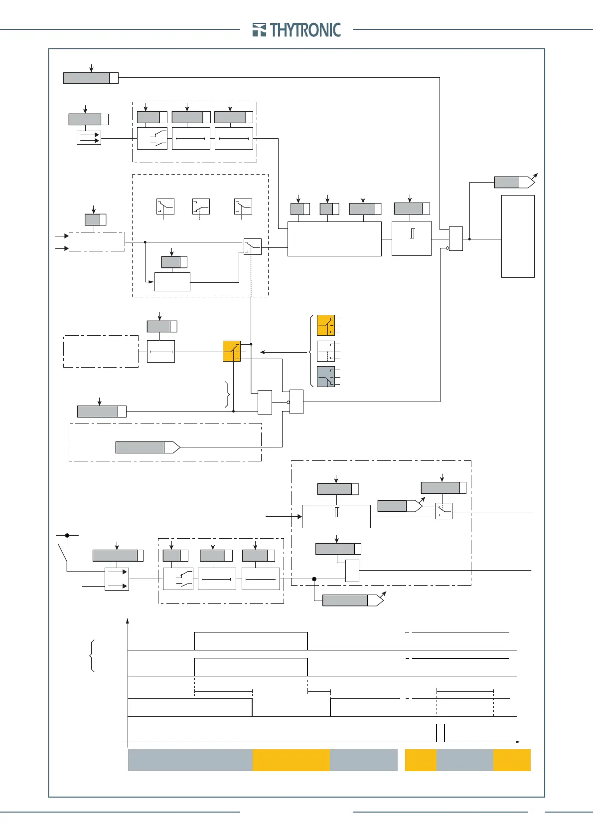
Thermal image (49) - Logic diagram of the second alarm threshold
Starting control set
Starting
control
&
CLP source
MR Enable
CB-State
I
RUN
=0.1
I
B
Max[I
L1...
I
L3
]
≥
I
RUN
I
L1...
I
L3
Output t
CLP
t
CLP
Max[I
L1...
I
L3
]
≥
I
RUN
Max[I
L1...
I
L3
]
≥
I
RUN
Max[I
L1...
I
L3
]
<
I
RUN
Starting detection
Reset CLP timer
CB State
CB OPEN CB CLOSED CB CLOSEDCB OPEN
t
I
RUN
t
CLP
0.1 s
HIGH THRESHOLD/
BLOCK
LOW THRESHOLD/
UNBLOCK UNBLOCK UNBLOCK
HIGH THRESHOLD/
BLOCK
HIGH THRESHOLD/
BLOCK
+UAUX
-UAUX
Binary input INx
T0
Logic
INx
t
ON
INx
t
ON
INx
t
OFF
0
n.o.
n.c.
INx
t
OFF
Motor restart
Motor restart
Motor restart
LOW TH. LOW TH.
Fun_49_AL2.ai
&
Dθ
≥
DthAL2
DthAL2
DthAL2
ON≡Enable element
TRIPPING MATRIX
(LED+RELAYS)
DthAL2 Enable
DthAL2-L
DthAL2-K
Block1, Block2
T0
t
DthCLP
DthCLPMode
t
DthCLP
A
B
C
Output t
DthCLP
Starting control set
A = ON - Change setting
B = OFF
C = ON - Element blocking
≥1
≥1
DThAL2 thermal image (49) block diagram
A
B
C
A = ON - Change setting
A
B
C
C = ON - Element blocking
A
B
C
B = OFF
Init DTheta
Binary input INx
T0
Logic
INx
t
ON
INx
t
ON
INx
t
OFF
T0
n.o.
n.c.
INx
t
OFF
I
th
K
ST
(
I
th
within CLP)
(
I
th
outside CLP)
I
th
/K
ST
A =“1”
A =“0”
Change
setting
Change
setting
Element
blocking
B or C
dDθ/dt + Dθ/T+ = (Ith/I
B
)
2
/T+
dDθ/dt + Dθ/T- = 0
T
+
T
-
DthIN
I
th
= √
I
1
2
+K
2
I
2
2
K
2
I
1
I
2
 Loading...


