146
NVA100X-D - Manual - 02 - 2016
FUNCTION CHARACTERISTICS
generator is connected to its own step-up transformer.
All elements can be enabled or disabled by setting ON or OFF the State parameters inside the
Set \ Profi le A(or B) \ Voltage controlled-restraint overcurrent 51V \ I-I/U> Element (I-I/U>> Ele-
ment) \ Defi nite time menus.
The trip of fi rst element may be inhibited by the start of the second element by setting ON the Disable
I-I/U> by start I-I/U>> (I-I/U>disbyI-I/U>>) parameter available inside the Set \Profi le A(or B) \
Voltage controlled-restraint overcurrent 51V \ I-I/U>> Element \ Setpoints menu.
An adjustable reset time delay is provided for every threshold (t
-I/U>RES
, t
-I/U>>RES
), useful for coor-
dination with electromechanical relays, in order to improve sensitivity against swings between the
generator and the grid, or to reduce intermittent fault elimination times.
Both the protection elements are blocked off whenever the VT supervision function is active, so
that no unwanted trip can arise if any fault on the VTs secondary circuits (break, fuse trip, etc) are
detect;
[1]
the Block functions enable from 74VT parameter (74VT-BK-EN) is available inside the
Set \ VT supervision -74VT menu.
Each overcurrent element can produce the Breaker Failure output if the I-I/U> BF, and/or I-I/U>
BF, parameters are set to ON. The parameters are available inside the Set \ Profi le A(or B) \ Voltage
controlled-restraint overcurrent 51V \ I-I/U> Element (I-I/U>> Element) \ Setpoints menus.
[2]
Note 1 The exhaustive treatment of the VT supervision function may be found inside the CONTROL AND MONITORING section.
Note 2 The common settings concerning the Breaker failure protection are adjustable inside the Breaker Failure - BF menu.
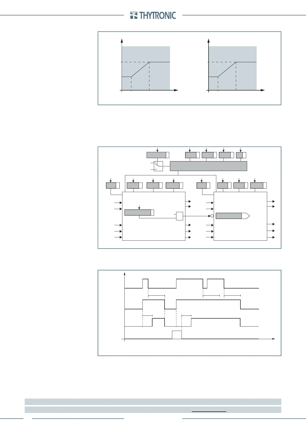
51V-VR_char.ai
First threshold Second threshold
U
-I/U-2
< U
-I/U-1
< U
-I/U-2
< U
-I/U-1
<
I
-I/U
>>
I
-I/U
>
KI
-I/U
>>KI
-I/U
>
Voltage Voltage
Current threshold Current threshold
Voltage controlled thresholds
General logic diagram of the voltage restraint-voltage controlled overcurrent elements - 51V
Block1
Block1
U
12
, U
23
, U
31
I
L1
, I
L2
, I
L3
U
12
, U
23
, U
31
I
L1
, I
L2
, I
L3
Block2 Block2
Block3
Block1
Block2
Block3
BF
Block1
Block2
BF
State
I
-I/U>>def
U
-I/U
< U
-I/U-1
< U
-I/U-2
<
K
t
-I/U>>def
t
-I/U>>RES
State
I
-I/U>def
I
-I/U
> Tr ip
I
-I/U
> S t ar t
I
-I/U
>> Trip
I
-I/U
>> Star t
I
-I/U
>> Star t
t
-I/U>def
t
-I/U>RES
Mode 51V>
Voltage controlled
Voltage restraint
I
-I/U
>
inhibition
I-I/U>> Element I-I/U> Element
Common configuration
ON=inhibit
&
I
-I/U
>
disby
I
-I/U
>>
START I-I/U>
TRIP I-I/U>
RESET
INPUT
Timers-F51V.ai
t
-I/U>RES
t
-I/U>def
t
-I/U>def
t
-I/U>RES
t
-I/U>RES
t
Voltage controlled-restraint overcurrent elements (51V) - Timers
 Loading...


