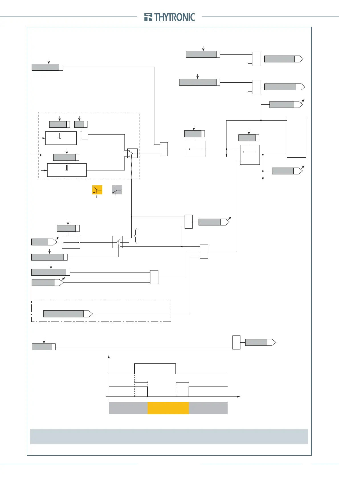
FUNCTION CHARACTERISTICS
171
NVA100X-D - Manual - 02 - 2016
t
EC>>>RES
T0
RESET
t
EC>>>def
0T
≥1
t
EC>>>def
t
EC>>>RES
Start IEC>>>
Trip IEC>>>
CB-State
Start I
2ndh>
ON≡Enable IEC>>> residual overcurrent element
Block1, Block2, Block4
&
IEC>>>ST-L
IEC>>>ST-K
IEC>>>TR-L
IEC>>>TR-K
T0
t
ECCLP>>>
&
2nd harmonic restraint enable (ON≡Enable)
IEC>>>2ndh-REST
IECCLP>>>Mode
t
ECCLP>>>
BF Enable (ON≡Enable)
IEC>>>BF
towards BF logic
IEC>>> BF
&
Trip IEC>>>
TRIPPING MATRIX
(LED+RELAYS)
A
B
C
A = ON - Change setting
B = OFF
C = ON - Element blocking
Output
t
ECCLP>>>
IEC>>> Enable
IEC>>> calculated residual overcurrent element Block diagram
t
ECCLP>>>
CB State CB OPEN CB CLOSED CB OPEN
Output t
ECCLP
>>
>
t
0.1 s
HIGH THRESHOLD/
BLOCK
LOW THRESHOLD/
UNBLOCK
HIGH THRESHOLD/
BLOCK
&
(ON≡
Inhibit
)
Start IEC>>>
Start IEC>>>
Start IEC>>>
(ON≡
Inhibit
)
IEC> inhibition
IEC>disbylE>>>
&
IEC>> inhibition
IEC>>disbylEC>>>
≥1
CLP IEC>>>
I
EC>>>def
A =“1”A =“0 or OFF”
I
EC
(Pickup within CLP)
(Pickup outside CLP)
I
ECCLP>>>def
I
EC
≥
I
ECCLP>>>def
&
State
I
EC>>>
≥
I
EC>>>def
Note Inside diagrams and text the IEC is the current residual current calculated by the vector sum of the currents
of the selected side (the H or L side)
Calculated residual overcurrent - 50N(Comp)/51N(Comp) - Third element logic diagram (IEC>>>) Sheet 1 of 2
 Loading...


