174
NVA100X-D - Manual - 02 - 2016
FUNCTION CHARACTERISTICS
If the CB position control is enabled (CB-55 = ON available inside the Set \ Profi le A(o B) \ Mini-
mum power factor - 55 \ Cphi< Element \ Setpoints menu) the start is issued when the following
conditions are meet:
1) cos
ϕ
< cos
ϕ
lag
< with Q ≥ 0 or cos
ϕ
< cos
ϕ
lead
< with Q < 0
2) Circuit Breaker closed
3) The t
ARM-cos
ϕ
<
timer (started when CB closes) is elapsed
If the CB position control is disabled (CB-55 = OFF) the start is issued when the following condi-
tion is meet:
1) cos
ϕ
< cos
ϕ
lag
< with Q ≥ 0 or cos
ϕ
< cos
ϕ
lead
< with Q < 0
After expiry of the associated operate time (t
CPhi1<
, t
CPhi2<
) a trip command is issued; if instead the
power factor exceed the threshold, the element is restored.
Breaker failure (BF)
The elements can produce the Breaker Failure output if the CPhi1< BF and/or CPhi2< BF param-
eters are set to ON. The parameters are available inside the Set \ Profi le A(o B) \ Minimum power
factor - 55 \ Cphi1< Element, Cphi2< Element \ Setpoints menus.
[1]
Logical block (Block1)
If the CPhi1<BLK1 and/or CPhi1<BLK1 enabling parameters are set to ON and a binary input is
designed for logical block (Block1), the concerning element is blocked off whenever the given input
is active.
[2]
The enabling parameter is available inside the Set \ Profi le A(o B) \ Minimum power fac-
tor - 55 \ Cphi1< Element, Cphi2< Element \ Setpoints menus, while the Block1 function must be
assigned to the selected binary input inside the Set \ Board 1(2) inputs \ Binary input IN1-1...(IN1-x)
menus.
All the named parameters can be set separately for Profi le A and Profi le B.
Note 1 The common settings concerning the Breaker failure protection are adjustable inside the Breaker Failure - BF menu.
Note 2 The exhaustive treatment of the logical block (Block 1) function may be found in the “Logic Block” paragraph inside CONTROL AND MONITOR-
ING section
•
•
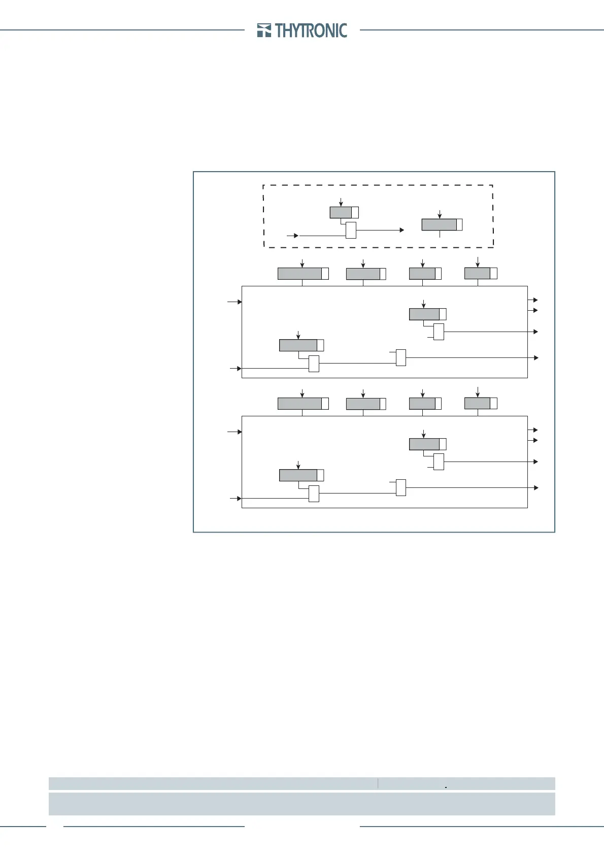
all-F55.ai
General logic diagram of the minimum power factor element - 55
CPhi1< Enable
55 Element - first threshold
Common
Start
CPhi1
<
Trip
CPhi1
<
Trip
CPhi1
<
Block1
BLK1
CPhi1<
&
CPhi1<BLK1
&
CPhi1<BF
Trip
CPhi1
<
&
CPhi1<BF
cosG
CPhi1<
t
CPhi1
<
t
ARM-CPhi<
CB
CB Closed
&
CB-55
t
ARM-CPhi<
CPhi1<
DIR
CPhi2< Enable
55 Element - second threshold
Start
CPhi2
<
Trip
CPhi2
<
Trip
CPhi2
<
Block1
BLK1
CPhi2<
&
CPhi2<BLK1
&
CPhi2<BF
Trip
CPhi2
<
&
CPhi2<BF
cosG
CPhi2<
t
CPhi2
<
CPhi2<
DIR
 Loading...


