FUNCTION CHARACTERISTICS
193
NVA100X-D - Manual - 02 - 2016
The operating mode may be selected by setting the Mode67N parameter, located inside the Set \
Profi le A(or B) \ Directional earth fault overcurrent-67N \ Common confi guration menu.
The settable operating mode is I (module) or I*cos (projection).
For both the operating modes, the polarizing reference used for displacement measure of the re-
sidual current may be selected:
Direct residual voltage - the measured U
E
voltage is employed.
Calculated residual voltage - the calculated U
EC
voltage is employed, where the fundamental com-
ponent and phase are derived from the instantaneous values of the three input phase-to-neutral
voltages.
Therefore, for both operating mode, the displacement of the residual current phasor I
E2
and the
residual voltage phasor (U
E
or U
EC
for direct/calculated residual voltage measurement type), positive
for lagging current compared with voltage (Φ
E
=(∠I
E2
- ∠U
E
, Φ
EC
=(∠I
E2
- ∠U
EC
).
The residual voltage measurement type may be selected by setting the 3Votype67N parameter,
located inside the Set \ Profi le A(or B) \ Directional earth fault overcurrent-67N \ Common confi gu-
ration menu. The measurement type is UE (direct measure of residual voltage) or UEC (calculated
residual voltage).
For each of the four thresholds (I
ED
>, I
ED
>>, I
ED
>>>, I
ED
>>>>), the characteristic angle (ϑ
E
>, ϑ
E
>>,
ϑ
E
>>>, ϑ
E
>>>>) may be adjusted (setting range 0…359° common for the three phases).
The the characteristic angle setting (positive when clockwise compared the polarizing voltage)
specifi es the angular displacement of the characteristic axis standing for the trip bisector of the
tripping zone. For isolated neutral systems with a 90° characteristic angle setting, faults towards
the LINE are detected, while with a 270° characteristic angle setting, faults towards the BUS are
detected. All the named parameters can be set separately for the four thresholds and for defi nite or
inverse time settings menu.
For each of the four thresholds (I
ED
>, I
ED
>>, I
ED
>>>, I
ED
>>>>), the half operating sector may be ad-
justed (setting range 0…180° simmetrically regarding the characteristic axis).
All the parameters can be set separately for the four thresholds and for defi nite or inverse time set-
tings menu.
•
•
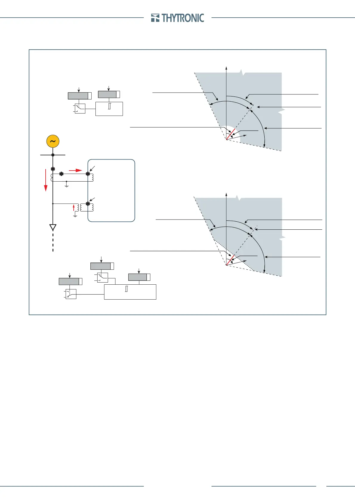
char-F67N-mode.ai
Operating characteristics of the earth fault overcurrent element - 67N
with module operating mode (I)
Operating characteristics of the earth fault overcurrent element - 67N
with projection operating mode ( I∙cos)
I
E
U
E
U
EC
Characteristic axis
Characteristic axis
Φ
E
o Φ
EC
Half operating sector
(β
E>
, β
E>>
, β
E>>>
, β
E>>>>
)
Half operating sector
(β
E>
, β
E>>
, β
E>>>
, β
E>>>>
)
Half operating sector
(β
E>
, β
E>>
, β
E>>>
, β
E>>>>
)
Half operating sector
(β
E>
, β
E>>
, β
E>>>
, β
E>>>>
)
Threshold (
I
ED threshold
):
(I
ED
>, I
ED
>>, I
ED
>>>, I
ED
>>>>)
(M∙I
ED
>, M∙I
ED
>>, M∙I
ED
>>>, M∙I
ED
>>>>)
Threshold (
I
ED threshold
):
(I
ED
>, I
ED
>>, I
ED
>>>, I
ED
>>>>)
(M∙I
ED
>, M∙I
ED
>>, M∙I
ED
>>>, M∙I
ED
>>>>)
I
E
Φ
E
o Φ
EC
Characteristic angle
Characteristic angle
(Θ
E>
, Θ
E>>
, Θ
E>>>
, Θ
E>>>>
)
(Θ
E>
, Θ
E>>
, Θ
E>>>
, Θ
E>>>>
)
U
E
U
EC
I
E
≥
I
ED threshold
I
ED threshold
I
E2
I
E2
I
I∙cos
Mode67N
I
E2
∙COS(
ϑ
E
-
Φ
E
)
≥
I
ED
threshold
I
ED threshold
I
E2
I
I∙cos
Mode67N
Φ
E
o Φ
EC
U
E
U
EC
3Votype67N
Trip sector
(toward line)
Trip sector
(toward line)
No trip sector
(toward busbar)
No trip sector
(toward busbar)
Operating characteristics of the ground directional overcurrent elements - 67N
NVA100X-D
BUSBAR
I
E
U
E
RESIDUAL
VOLTAGE INPUT
B9
C7
RESIDUAL
CURRENT INPUT
LINE
 Loading...


