FUNCTION CHARACTERISTICS
217
NVA100X-D - Manual - 02 - 2016
For each of the four thresholds (I
EDC
>, I
EDC
>>, I
EDC
>>>, I
EDC
>>>>), the characteristic angle (ϑ
E
>,
ϑ
E
>>, ϑ
E
>>>, ϑ
E
>>>>) may be adjusted (setting range 0…359° common for the three phases).
The the characteristic angle setting (positive when clockwise compared the polarizing voltage)
specifi es the angular displacement of the characteristic axis standing for the trip bisector of the
tripping zone. For isolated neutral systems with a 90° characteristic angle setting, faults towards
the LINE are detected, while with a 270° characteristic angle setting, faults towards the BUS are
detected. All the named parameters can be set separately for the four thresholds and for defi nite or
inverse time settings menu. For each of the four thresholds (I
EDC
>, I
EDC
>>, I
EDC
>>>, I
EDC
>>>>) the
half operating sector may be adjusted (setting range 0…180° simmetrically regarding the character-
istic axis). All the parameters can be set separately for the four thresholds and for defi nite or inverse
time settings menu.
VT supervision
For all the four thresholds I
EDC>
, I
EDC>>
,
I
EDC>>>
, I
EDC>>>>
, the operating mode when the 74VT function
is active may be defi ned:
OFF: no action are issued by 74VT.
Block: all the four thresholds are blocked when the 74VT function is active.
Not directional: all the four thresholds are switched from directional to not directional criteria
when the 74VT function is active.
The 74VT information may issued from internal 74VT function or from an external signal acquired by
means a binary input.
If a binary input is designed for 74VText, for all the four thresholds, the operating mode when the 74VT
function is active may be defi ned:
OFF: no action are issued by 74VT.
Block: all the four thresholds are blocked when the 74VT external signal is active.
Not directional: all the four thresholds are switched from directional to not directional criteria
when the 74VT external signal is active.
Malfunctioning of the directional overcurrent elements can be avoided when VTs secondary fault
will arise (fuse or MCB tripping) by switching the overcurrent directional to non directional overcur-
rent protection
The 74VTint67NC and 74VText67NC parameters may be set as OFF, Block, Not directional
inside the Set \ Profi le A(or B) \ Directional earth fault overcurrent-67N(Comp) \ Common confi gura-
tion menu, while the 74VText function must be assigned to the selected binary inputs inside the Set
\ Board 1(2) inputs \ Binary input IN1-1...(IN1-x) menus.
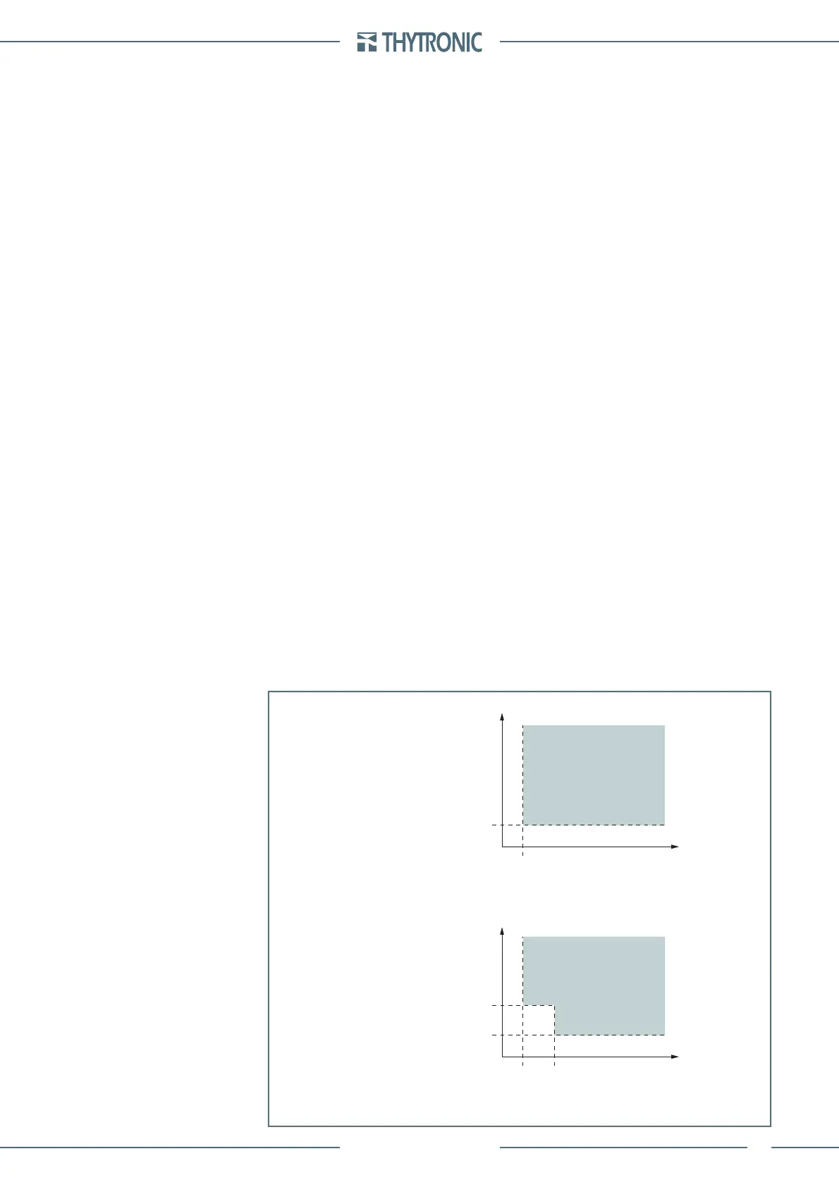
For all the four thresholds (common for all thresholds) an insensibility zone may be enabled in the
voltage-current plane.
If enabled, the insensibility zone is user adjustable by means the M multiplier (common for all thresh-
olds); the rectangle defi ned by the current and voltage thresholds and the same multiplied by M
becomes a No trip zone.
Such insensibility zone may be useful to avoid unwanted trip in the presence of some fi xed residual
current and/or voltage (e.g. CT and or VT errors in the residual measurements).
The Insens-Zone(C) (OFF, ON) and M(C) parameters may be adjusted inside the Set \ Profi le A(or
B) \ Directional earth fault overcurrent-67N(Comp) \ Common confi guration menu.
•
•
•
•
•
•
char-F67NC-IeUe.ai
Voltage/current characteristic concerning the earth fault overcurrent element - 67N(Comp)
with insensibility zone disabled
Voltage/current characteristic concerning the ground directional overcurrent - 67N(Comp)
with insensibility zone enabled
I
E2
I
EDC
>, I
EDC
>>, I
EDC
>>>, I
EDC
>>>>
M∙I
EDC
>, M∙I
EDC
>>, M∙I
EDC
>>>, M∙I
EDC
>>>>
M∙U
ED
>, M∙U
ED
>>, M∙U
ED
>>>, M∙U
ED
>>>>
TRIP
U
E
U
EC
I
E2
I
EDC
>, I
EDC
>>, I
EDC
>>>, I
EDC
>>>>
U
ED
>, U
ED
>>, U
ED
>>>, U
ED
>>>>
U
ED
>, U
ED
>>, U
ED
>>>, U
ED
>>>>
TRIP
U
E
U
EC
 Loading...


