FUNCTION CHARACTERISTICS
219
NVA100X-D - Manual - 02 - 2016
that is the -β
E
≤ (Θ
E
-Φ
E
) ≤ +β
E
condition is fulfi lled.
[1]
If the operation mode is switched to “not directional” (by the 74VT function), the start of any 67N
threshold becomes active when the following is complied:
- The residual current (I
E
) fundamental component overcomes the threshold (I
EDC>
, I
EDC>>
,
I
EDC>>>
,
I
EDC>>>>
)
For both the operating mode (module or projection), when the start signal goes ON a concerning
counter starts; after expiry of the associated operate time (t
EDC>
, t
EDC>>
,
t
EDC>>>
, t
EDC>>>>
) a trip com-
mand is issued, if instead the above conditions don’t remain valid, the element it is restored.
All the parameters are located inside the menus concerning the four elements, separately for defi -
nite and inverse time characteristics.
Example: the operate time concerning the fi rst threshold with defi nite time characteristic (IEDC>def)
is available inside the Set \ Profi le A(or B) \ Directional earth fault overcurrent-67N(Comp) \
IEDC> Element \ Defi nite time menu.
All directional earth fault overcurrent elements can be enabled or disabled by setting ON or OFF the
IEDC> Enable, IEDC>> Enable, , IEDC>>> Enable e/o IEDC>>>> Enable parameters in-
side the Set \ Profi le A(or B)\Directional earth fault overcurrent-67N(Comp) \ IEDC> Element (IEDC>>
Element, IEDC>>> Element, IEDC>>> Element) \ Setpoints menus.
The fi rst and second overcurrent element can be programmed with defi nite or inverse time char-
acteristic by setting theIEDC>Curve and/or IEDC>>Curve (DEFINITE, IEC/BS A, IEC/BS
B, IEC/BS C, ANSI/IEE MI, ANSI/IEE VI, ANSI/IEE EI, EM) available inside the Set \ Profi le
A(or B) \ Directional earth fault overcurrent-67N(Comp) \ IEDC> Element (IEDC>> Element) \ Set-
points menus.
The trip of IEDC> element may be inhibited by the start of the second, third and/or fourth element
(I
EDC>>
,
I
EDC>>>
, I
EDC>>>>
) by setting ON the Disable IEDC> by start IEDC>>, Disable IEDC> by start
IEDC>>>, Disable IEDC> by start IEDC>>>> (IEDC>disbyIEDC>>, IEDC>disbyIEDC>>>,
IEDC>disbyIEDC>>>>) parameters available inside the Set \ Profi le A(or B) \ Directional earth
fault overcurrent-67N(Comp) \ IEDC>> Element (IEDC>>> Element, IEDC>>>> Element) \ Setpoints
menus.
Similarly the trip of the:
IEDC>> element may be inhibited by start of the third and/or fourth element (IEDC>>> and/or IEDC>>>>)
by setting ON the Disable IEDC>> by start IEDC>>>, start IEDC>>>> (IEDC>>disbyIEDC>>>,
IEDC>>disbyIEDC>>>>) parameter available inside the Set \ Profi le A(or B) \ Directional
earth fault overcurrent-67N(Comp) \ IEDC>>> Element (IEDC>>>> Element) \ Setpoints menus.
IEDC>>> element may be inhibited by start of the fourth element (IEDC>>>>) by setting ON the Dis-
able IEDC>>> by start IEDC>>>> (IEDC>>>disbyIEDC>>>>) parameter available inside the
Set \ Profi le A(or B) \ Directional earth fault overcurrent-67N(Comp) \ IEDC>>>> Element \ Setpoints
menu.
All the named parameters can be set separately for Profi le A and Profi le B.
An adjustable reset time delay is provided for every threshold
(t
EDC>RES
, t
EDC>>RES
, t
EDC>>>RES
, t
EDC>>>>RES
).
Breaker failure (BF)
Each directional earth fault element can produce the Breaker Failure output if the IEDC> BF,
IEDC>> BF, IEDC>>> BF and/or IEDC>>>> BF parameters are set to ON. The param-
eters are available inside the Set \ Profi le A(or B) \ Directional earth fault overcurrent-67N(Comp) \
IEDC> Element (IEDC>> Element, IEDC>>> Element, IEDC>>> Element) \ Setpoints menus.
[2]
Cold load pickup (CLP)
If the CLP function (Cold Load Pick-up) is enabled for element blocking, the selected threshold may
be blocked for an adjustable time interval, starting from the circuit breaker closure.
This operating mode may be select by setting ON-Element blocking the IEDCCLP> Mode,
IECDCLP>> Mode, IEDCCLP>>> Mode, IEDCCLP>>>> Mode parameters.
Note 1 For each threshold the projection of the residual current phasor on the characteristic axis is: (I
ECH
or I
ECL
)cos(Θ
E
>-Φ
E
), I (I
ECH
or I
ECL
)cos(Θ
E
>>-
Φ
E
), (I
ECH
or I
ECL
)cos(Θ
E
>>>-Φ
E
), (I
ECH
or I
ECL
)cos(Θ
E
>>>>-Φ
E
) when “direct” residual voltage is selected (U
E
), or
I
ECH
or I
ECL
)cos(Θ
E
>-Φ
EC
), (I
ECH
or I
ECL
)cos(Θ
E
>>-Φ
EC
), (I
ECH
or I
ECL
)cos(Θ
E
>>>-Φ
EC
), (I
ECH
or I
ECL
)cos(Θ
E
>>>>-Φ
EC
) when “calculated”
residual voltage is selected (U
EC
). The Θ
E
, β
E
and Φ
EC
symbols are not used inside the Thysetter and MMI menus.
Note 2 The common settings concerning the Breaker failure protection are adjustable inside the Breaker Failure - BF menu.
•
•
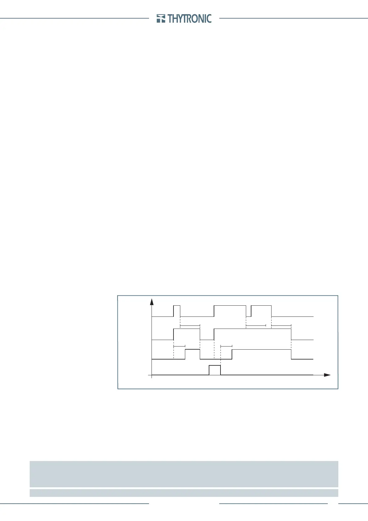
Timers-F67NC.ai
IEDC> Start
IEDC> Trip
t
EDC>
t
EDC>
RESET
INPUT
t
EDC>RES
t
EDC>RES
t
EDC>RES
t
67N(Comp) element timers - 67N(Comp) (first element)
 Loading...


