INSTALLATION
295
NVA100X-D - Manual - 02 - 2016
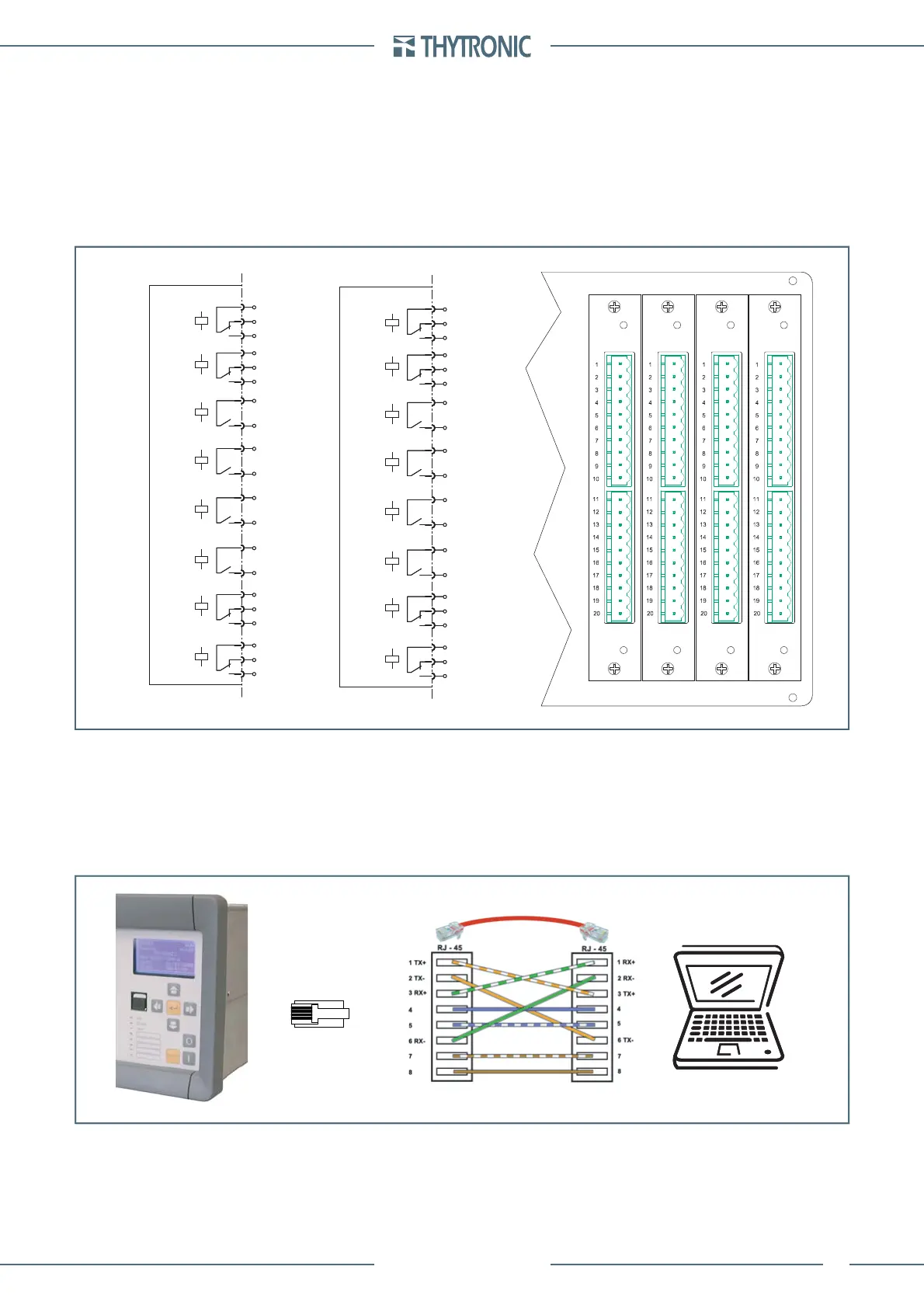
Output relays
The the base confi guration includes 16 logic inputs (IN1-1. .. IN1-16) and 8 output relays (KC1-1. ..
KC1-8) and can be expanded with:
One board (OC2F) with eight relays KC2-1...KC2-8 and one board (IN2D) with with sixteen binary
inputs (IN2-1...IN2-16)
One board (OC2F) with eight relays KC2-1...KC2-8 and one board with a IRIG-B port
It is advisable to verify that the technical characteristic of the contacts be suitable for the applied
load (about current, nominal voltage, make and break current , etc..).
All contacts are shown in de-energized state for standard reference.
IRIG-B
The following time synchronization methods are available:
• SNTP protocol (Simple Network Time Protocol) over Ethernet network
• IRIG-B (Inter-Range Instrumentation Group – Time Code Format B)
Local port
A cross cable must be employed.
When used the local port takes priority over the Ethernet port
•
•
Output relays
OUTPUT RELAYS
1
3
2
4
6
5
15
17
16
18
20
19
9
10
7
8
11
12
13
14
OC1E
KC1-1
KC1-2
KC1-3
KC1-4
KC1-5
KC1-6
KC1-7
KC1-8
OUTPUT RELAYS
1
3
2
4
6
5
15
17
16
18
20
19
9
10
7
8
11
12
13
14
OC2F
KC2-1
KC2-2
KC2-3
KC2-4
KC2-5
KC2-6
KC2-7
KC2-8
IN2D IN1C OC1EOC2F
Output relays
OUTPUT RELAYS
1
3
2
4
6
5
15
17
16
18
20
19
9
10
7
8
11
12
13
14
OC1E
KC1-1
KC1-2
KC1-3
KC1-4
KC1-5
KC1-6
KC1-7
KC1-8
OUTPUT RELAYS
1
3
2
4
6
5
15
17
16
18
20
19
9
10
7
8
11
12
13
14
OC2F
KC2-1
KC2-2
KC2-3
KC2-4
KC2-5
KC2-6
KC2-7
KC2-8
IN2D IN1C OC1EOC2F
serial1-sch.ai
RJ45
serial1-sch.ai
RJ45
 Loading...


