FUNCTION CHARACTERISTICS
79
NVA100X-D - Manual - 02 - 2016
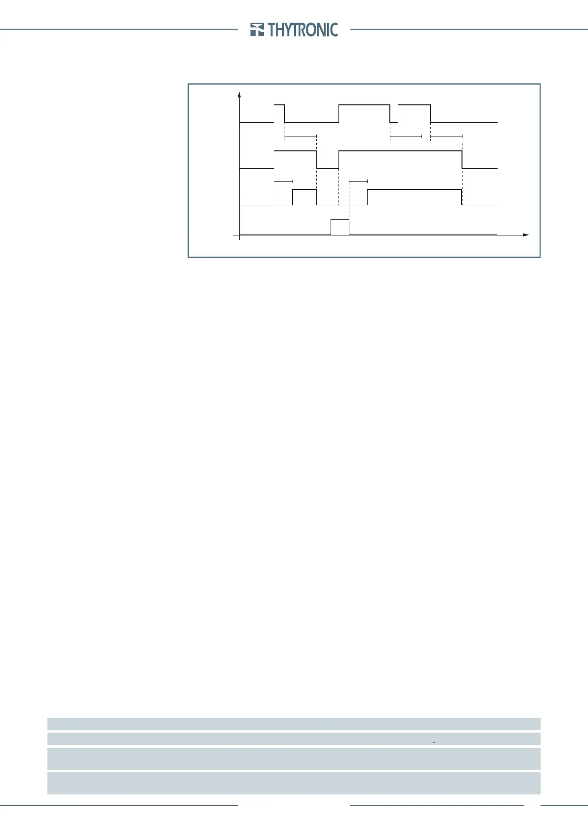
For each threshold a reset time can be set (t
Z<RES
e t
Z<<RES
) used for coordination with electrome-
chanical relays, in order to protect sensitive to swings between the generator and the network or
clearing time for intermittent faults.
VT monitoring (74VT)
The protection elements are blocked off whenever the VT supervision function are active, so that no
unwanted trip can arise if any fault on the VTs secondary circuits (break, fuse trip, etc) are detect;
[1]
the 74VT block enabled parameter is available inside the Set \ VT supervision -74VT \ Setpoints
menu.
Breaker failure (BF)
Each element can produce the Breaker Failure output if the BF element parameters are set to
ON available inside the Set \ Profi le A(or B) \ Underimpedance - 21 \ Z< Element (Z<< Element ) \
Setpoints menus.
[2]
Logical block (Block1)
If the Z<BLK1, Z<<BLK1 enabling parameters are set to ON and a binary input is designed
for logical block (Block1), the concerning element is blocked off whenever the given input is ac-
tive.
[3]
The enabling parameters are available inside the Set \ Profi le A(or B) \ Underimpedance-
21 \ Z< Element (Z<< Element) \ Setpoints menus, while the Block1 function must be assigned to the
selected binary input inside the Set \ Board1(2) inputs \ Binary input IN1-1...INx-x menus.
Selective block (Block2)
All along the protective elements the selective block may be set.
The logic selectivity function may be performed by means any combination of the following I/O:
One committed pilot wire input (BLIN1).
One or more binary inputs designed for input selective block.
One committed pilot wire output (BLOUT1).
One or more output relays designed for output selective block.
Only when the committed pilot wire are used the continuity check of the pilot wire link is active.
Use of committed pilot wire input BLIN1:
The protection is blocked off according the selectivity block criteria when the input BLIN1 is active.
The information about phase or phase+earth block may be select programming the ModeBLIN1
parameter inside the Set \ Profi le A(or B) \ Selective block-BLOCK2 \ Selective block IN menus.
Use of binary inputs:
If the Z<BLK2IN and/or Z<<BLK2IN parameters are set to ON and a binary input is designed
for selective block (Block2), the protection is blocked off by phase elements (Block2 Iph) or by
any protection element (Block2 Iph/IE) according the selectivity block criteria.
[4]
The enable
Z<BLK2IN, Z<BLK2IN parameters are available inside the Set \ Profi le A(or B) \ Underimped-
ance-21 \ Z< Element (Z<< Element) \ Setpoints menus, while the Block2 Iph and Block2 Iph/IE
functions must be assigned to the selected binary inputs inside the Set \ Board1(2) inputs \ Binary
input IN1-1...INx-x menus.
Use of committed pilot wire output BLOUT1:
The information about phase or phase+earth block may be select programming the ModeBLOUT1
parameter (OFF - ON IPh - ON IPh/IE - ON IE) inside Set \ Profi le A(or B) \ Selective block-
BLOCK2 \ Selective block OUT menus.
Note 1 The exhaustive treatment of the VT and CT supervision function may be found inside the CONTROL AND MONITORING section.
Note 2 The common settings concerning the Breaker failure protection are adjustable inside the Breaker Failure - BF menu.
Note 3 The exhaustive treatment of the logical block (Block 1) function may be found in the “Logic Block” paragraph inside CONTROL AND MONITOR-
ING section
Note 4 The exhaustive treatment of the selective block (Block 2) function may be found in the “Selective Block” paragraph inside CONTROL AND
MONITORING section
•
•
•
•
•
•
•
t
Z
< t
Z
<
Start Z<
Trip Z<
RESET
INPUT
Timers-F21.ai
t
Z<RES
t
Z<RES
t
Z<RES
t
First element underimpedance timers - 21
t
Z
< t
Z
<
Start Z<
Trip Z<
RESET
INPUT
Timers-F21.ai
t
Z<RES
t
Z<RES
t
Z<RES
t
First element underimpedance timers - 21
 Loading...


