FUNCTION CHARACTERISTICS
87
NVA100X-D - Manual - 02 - 2016
Fun-F27_S1.ai
≥1
U< Inhibition
(ON≡
Inhibit
)
Block 74VT
VT fault (74VT)
(=0 without fault)
U< Curve
0T
RESET
t
U<
0T
TRIPPING MATRIX
(LED+RELAYS)
t
U<def
t
U<inv
Start U<
U<ST-K
Start U<
U<TR-K
U<ST-L
U<TR-L
Trip U<
Trip U<
Trip U<
BF Enable (ON≡Enable)
U<BF
towards BF logic
&
BLK1U<
U< BF
&
&
&
Enable (ON≡Enable)
Block1 input (ON≡Block)
U<BLK1
Block1
Block1
Logic27
≥1
&
Utype27
U
L1
U
12
U
L2
U
23
U
L3
U
31
Binary input INx
T0
Logic
INx
t
ON
INx
t
ON
INx
t
OFF
T0
n.o.
n.c.
INx
t
OFF
≥1
&
State
U<
inv
U ≤
U<
def
U ≤
U<
inv
U<
def
&
State
ON≡Enable U< undervoltage element
U< Enable
&
(ON≡
Inhibit
)
Disable 27 function by operator
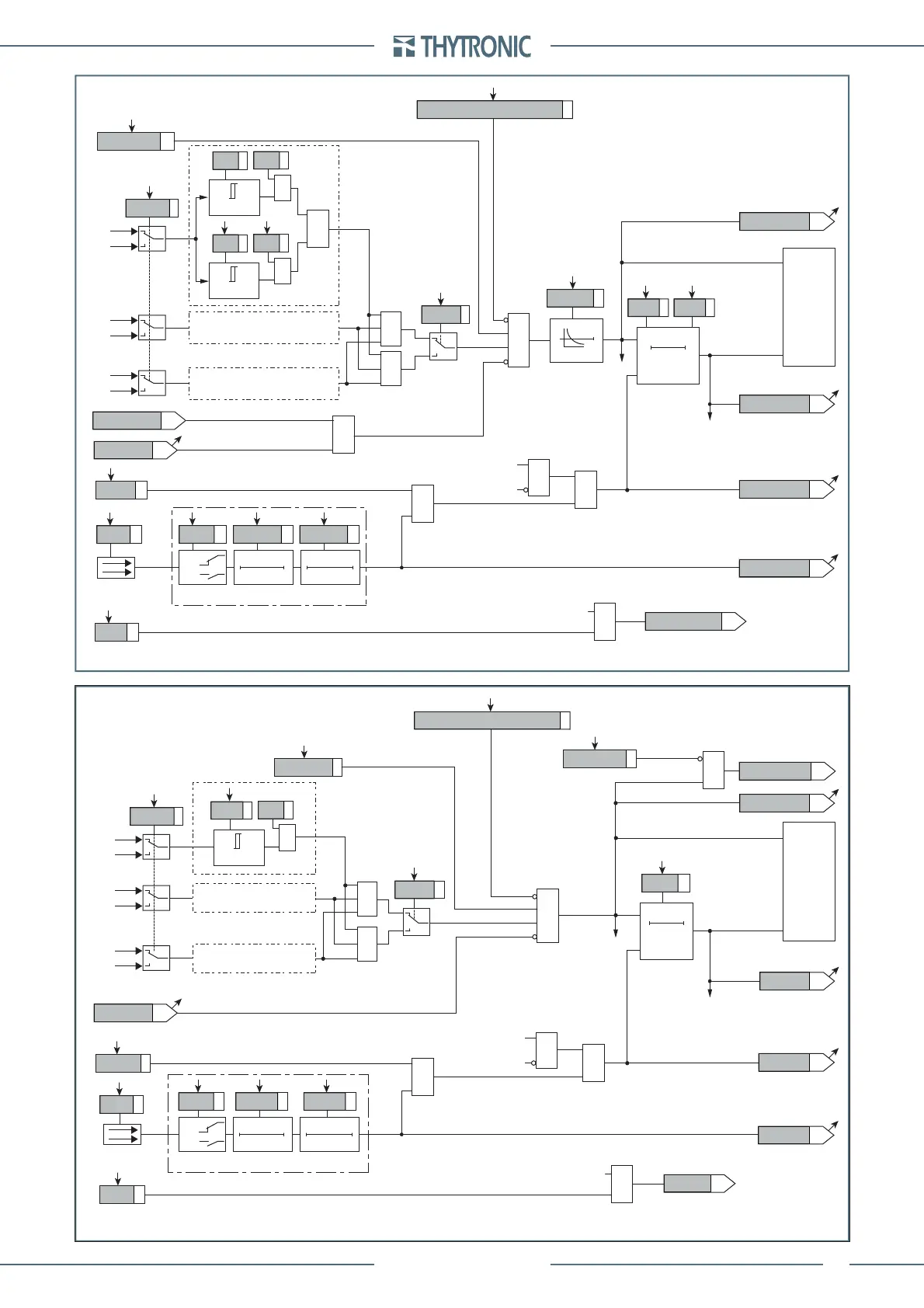
Logic diagram concerning the first threshold (U<) of the undervoltage element - 27
Fun-F27_S2.ai
Block 74VT
VT fault (74VT)
(=0 without fault)
RESET
t
U<<
0T
TRIPPING MATRIX
(LED+RELAYS)
t
U<<def
Start U<<
Trip U<<
Start U<<
Trip U<<
Trip U<<
BF Enable (ON≡Enable)
towards BF logic
&
U<< BF
&
&
&
Enable (ON≡Enable)
Block1 input (ON≡Block)
Block1
Block1
&
(ON≡
Inhibit
)
U< Inhibition
U<disbyU<<
Binary input INx
T0
Logic
INx
t
ON
INx
t
ON
INx
t
OFF
T0
n.o.
n.c.
INx
t
OFF
U<<ST-K
U<<TR-K
U<<ST-L
U<<TR-L
U<<BF
BLK1U<<
U<<BLK1
Logic27
≥1
&
Utype27
U
L1
U
12
U
L2
U
23
U
L3
U
31
&
State
U ≤
U<<
def
U<<
def
&
ON≡Enable U<< element
U<< Enable
(ON≡
Inhibit
)
Disable 27 function by operator
Logic diagram concerning the second threshold (U<<) of the undervoltage element - 27
 Loading...


