Document Ref 941113-001 Rev 2 Page 5-11
Quantium 310 Maintenance Manual Maintenance Procedures - Electronics
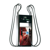
4) REMOVAL OF WWC COVER ASSEMBLY:-
•Locate the WWC cover assembly (including Mainboard and I/O
Board where fitted) on the WWC centre plate on side A of the
dispenser.
•Use wirecutters to cut the W&M seals on the heat sinks on the
bottom of the WWC cover.
•Locate the connectors and cables on the WWC cover. Disconnect
ALL connectors and cables from the WWC cover.
Note: Take care to note the position of the connector(s) on the
WWC cover.
•Use the crosshead screwdriver to loosen the four screws on the
WWC cover key slots.
•Carefully remove the WWC cover assembly from the WWC centre
plate.
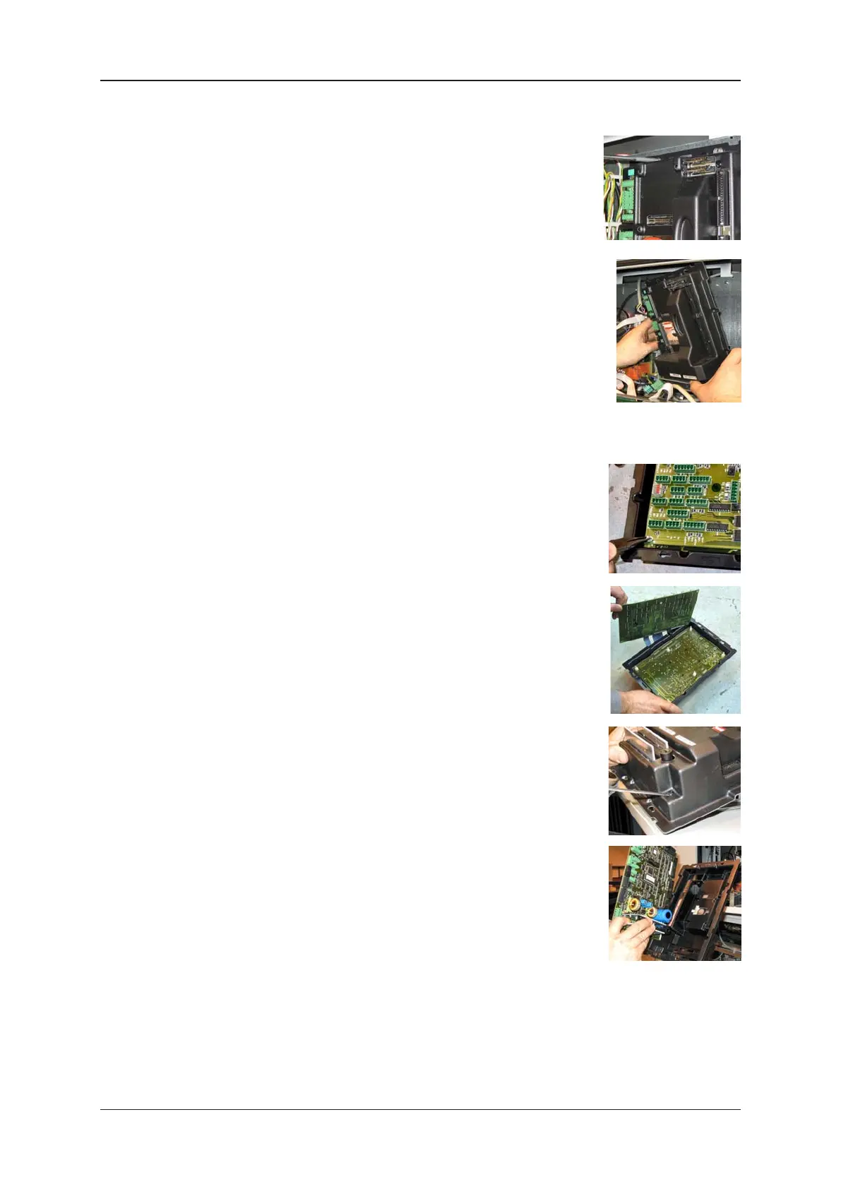
5) REMOVAL OF I/O BOARD (WHERE FITTED):-
•Locate the I/O Board on the WWC cover assembly.
•Use the long nose pliers to squeeze the plastic pillars to release
the I/O Board.
•Carefully remove the I/O Board from the WWC mainboard.
6) REMOVAL OF MAINBOARD:-
•Remove I/O Board as described (where fitted).
•Use a flathead screwdriver to loosen and remove the four plastic
rivets on the WWC cover to release the mainboard.
•Carefully remove the mainboard from the WWC centre plate cover.
•Position the new mainboard and re-fit the four plastic rivets to
secure to the WWC cover.
7) If removed, fit the (new) I/O Board onto the plastic pillars on the
WWC cover using long nose pliers.
8) Re-fit the WWC cover assembly (including Mainboard and I/O Board where fitted) to the
WWC and secure by tightening the four screws.
9) Re-connect ALL cable and connectors to the WWC mainboard.