2-4 Tolomatic User Guide: ICR Rod Style Integrated Control Actuator
The ICR SV1B Basic actuator has a total of 8 digital inputs / 4 are spare and not
implemented. These digital inputs are opto-isolated from the actuator’s drive
circuitry and can be wired as either sinking or sourcing. All of the digital inputs have
a common return. Figure 2-6 shows the circuit diagram for the interface.
Figure 2-6: ICR SV1B Basic Actuator Interface Circuit Diagram
2.2 Digital Inputs – ICR SV1B Basic Actuator
4.7K
2K
INPUT COMMON
INPUT
TO INTERNAL
CIRCUITRY
2 : ICR SV1B BASIC - ELECTRICAL INTERFACE, SPECS & WIRING
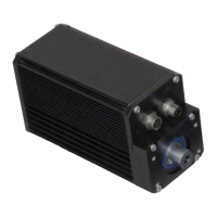
2.1.3 Cable Routing
Over time, liquid contaminants such as oil and cleaning solutions may accumulate
on the cables and in the connectors if they are an exposed type. To minimize the
introduction of contaminants into the connector, route the cables so that there is a
loop in the cable just prior to its attachment to the connector.
Two examples are shown below depending on the orientation of the connectors.
Units mounted in such a way that the connectors are on the bottom surface of the
actuator require no looping.
Top
Mount
Loop
Side
Mount
Loop
Figure 2-5: Cable Routing for Top and Side Mounted Connectors