Receiver Housing Overview
5
P/N: 1004636-01
Getting Acquainted
Back Panel View
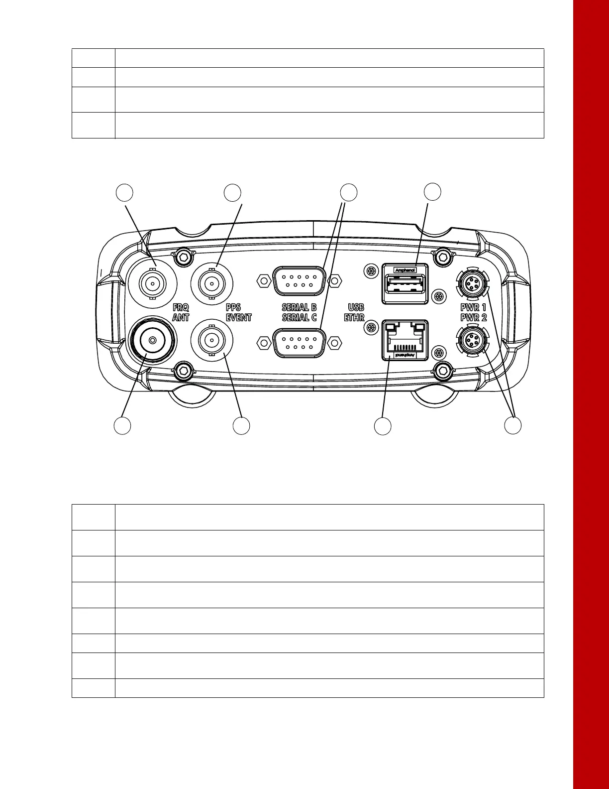
Figure 4: Receiver – Back Panel View
4
• FN Button – Turns data recording on and off.
5
• Power Button – Turns the receiver on and off; puts the unit in Sleep mode.
6
• SIM Card Slot – Resides on the front panel under the door and connects the SIM card to the receiver
board to provide cellular connectivity.
7
• SD Card Slot – Resides on the front panel under the door and connects the SD card to the receiver board
to provide memory.
Table 1. Font Panel Ports
Table 2. Back Panel Ports
1
• External Frequency Port (BNC Connector) – Used for an external frequency input or the receiver’s internal
frequency output.
2
• PPS Port (BNC Connector) – Used for generating one pulse per second signals with programmable
reference time, period, and offset. The pulse is synchronized to a specified reference time.
3
• Serial Ports (x3) – Used for communication between the receiver and an external device.
Ports A and B are RS-232. Port C is RS-422.
4
• USB Type A – Used for high-speed data transfer and communication between the receiver and an
external device.
5
• Power Ports (x2) – Connects the receiver to external power sources. PWR1 supplies power to receiver
and charges internal backup battery. PWR2 does not charge the batteries.
6
• Ethernet – Used to connect the receiver to a computer or network.
7
• Event Marker Port (BNC Connector) – Used to input an event synchronized with a specified time
reference.
8
• GNSS Antenna Port (Type N Connector) – Used for detecting GNSS signals.