Figure15
6.Pushthecasterspindlethroughthefrontcasterarm
andinstalltheshims(astheywereoriginallyinstalled)
andtheremainingspacersontothespindleshaft.
7.Installthetensioningcaptosecuretheassembly.
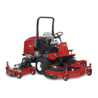
8.Removethehairpincotterandclevispinsecuringthe
height-of-cutchainstotherearofthemowerdeck
(Figure16).
Figure16
1.Height-of-cutchain2.Clevispinandhairpin
cotter
9.Mounttheheight-of-cutchainstothedesired
height-of-cutholewiththeclevispinandhairpincotter
(Figure17).
Figure17
Note:Whenusing25mm(1inch),38mm(1-1/2inch),
or51mm(2inch)heightsofcut,movetheskidsandgauge
wheelstothehighestposition.
WingMowerDecks
Toadjusttheheightofcutonthewingmowerdecks,add
orremoveanequalnumberofspacersfromthecaster
forks,positionthecaster-wheelaxlesinthehighorlow
height-of-cutholesinthecasterforks,andsecurethepivot
armstotheselectedheight-of-cutbracketholes.
1.Positionthecaster-wheelaxlesinthesameholesinall
ofthecasterforks(Figure18andFigure20).
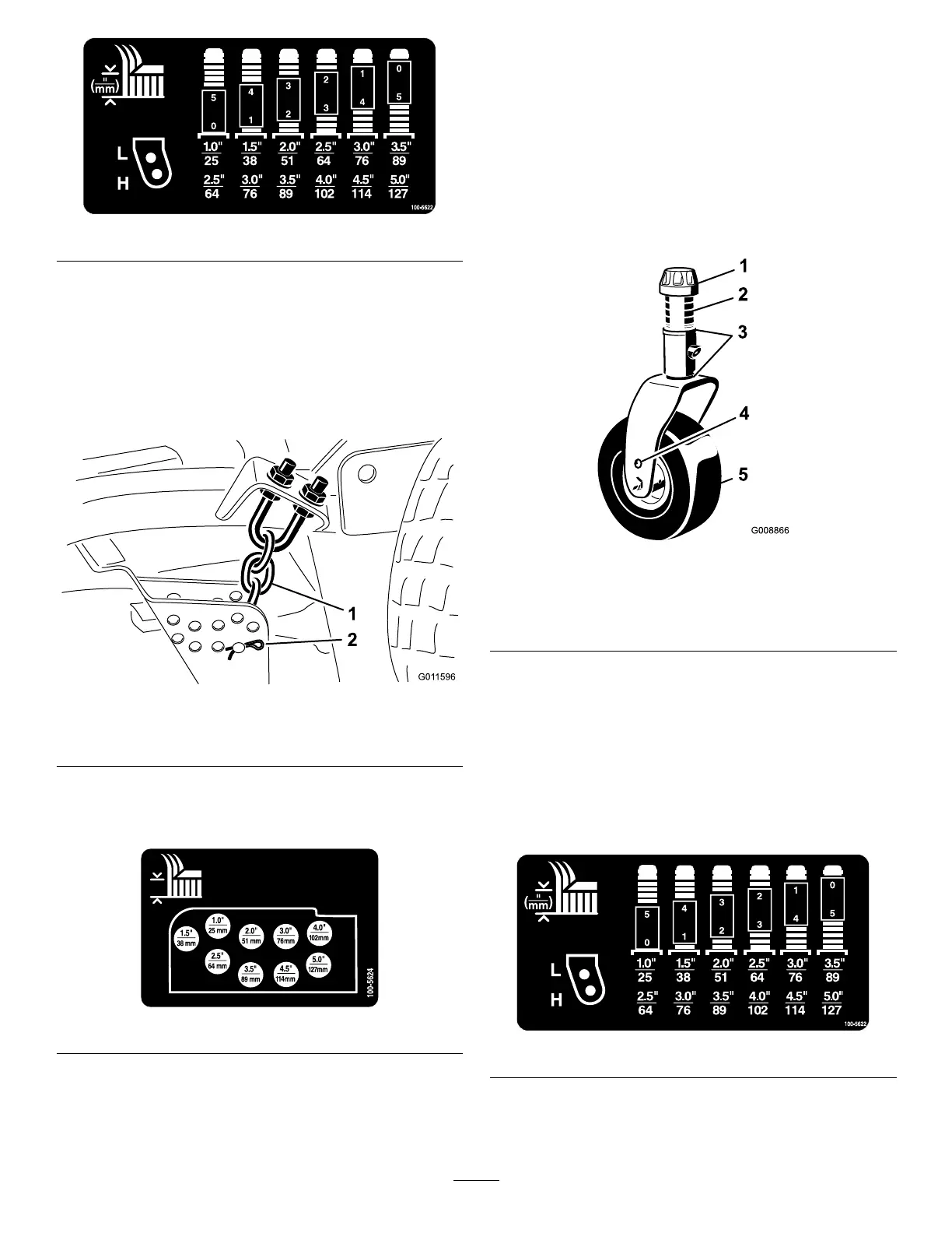
2.Removethetensioningcapfromthespindleshaftand
slidethespindleoutofthecasterarm(Figure18).
Figure18
1.Tensioningcap4.Topaxle-mountinghole
2.Spacers5.Casterwheel
3.Shims
3.Installthe2shimsontothespindleshaftastheywere
originallyinstalled.
Note:Theseshimsarerequiredtoachievealevel
acrosstheentirewidthofthemowerdecks.Slidethe
appropriatenumberof13mm(1/2inch)spacersonto
thespindleshafttogetthedesiredheight-of-cut;then
slidethewasherontotheshaft.
Refertothefollowingcharttodeterminethe
combinationsofspacersforthesetting(Figure19).
Figure19
4.Pushthecasterspindlethroughthefrontcasterarm
andinstalltheshims(astheywereoriginallyinstalled)
andtheremainingspacersontothespindleshaft.
24