Figure 30
1. Boom bypass valves
13. T ur n the boom on and off to v erify the
pressure does not c hang e .
14. R e peat ste ps 11 through 13 for the other
booms .
15. Dri v e the spra yer at the desired speed while
spra ying and tur n eac h boom off indi vidually .
T he pressure on the g aug e should not c hang e .
Pump
T he pump is located near the front of the tank on
the right side ( Figure 31 ).
Figure 31
1. Pump
3. Pressure dampener
2. Grease tting
Adjusting the Air Pressure in
Dampener
T he air pressure in the dampener on the pump is
set at 15 psi (1 bar) b y the man ufacturer . T his is
recommended for nozzle spra y pressures betw een
20 psi (1.3 bar) and 45 psi (3 bar). If different
nozzle pressures are required, set pressure
dampener at pressures indicated.
Nozzle
Dampener
40 psi/2.7 bar 12–14 psi/0.8–0.9 bar
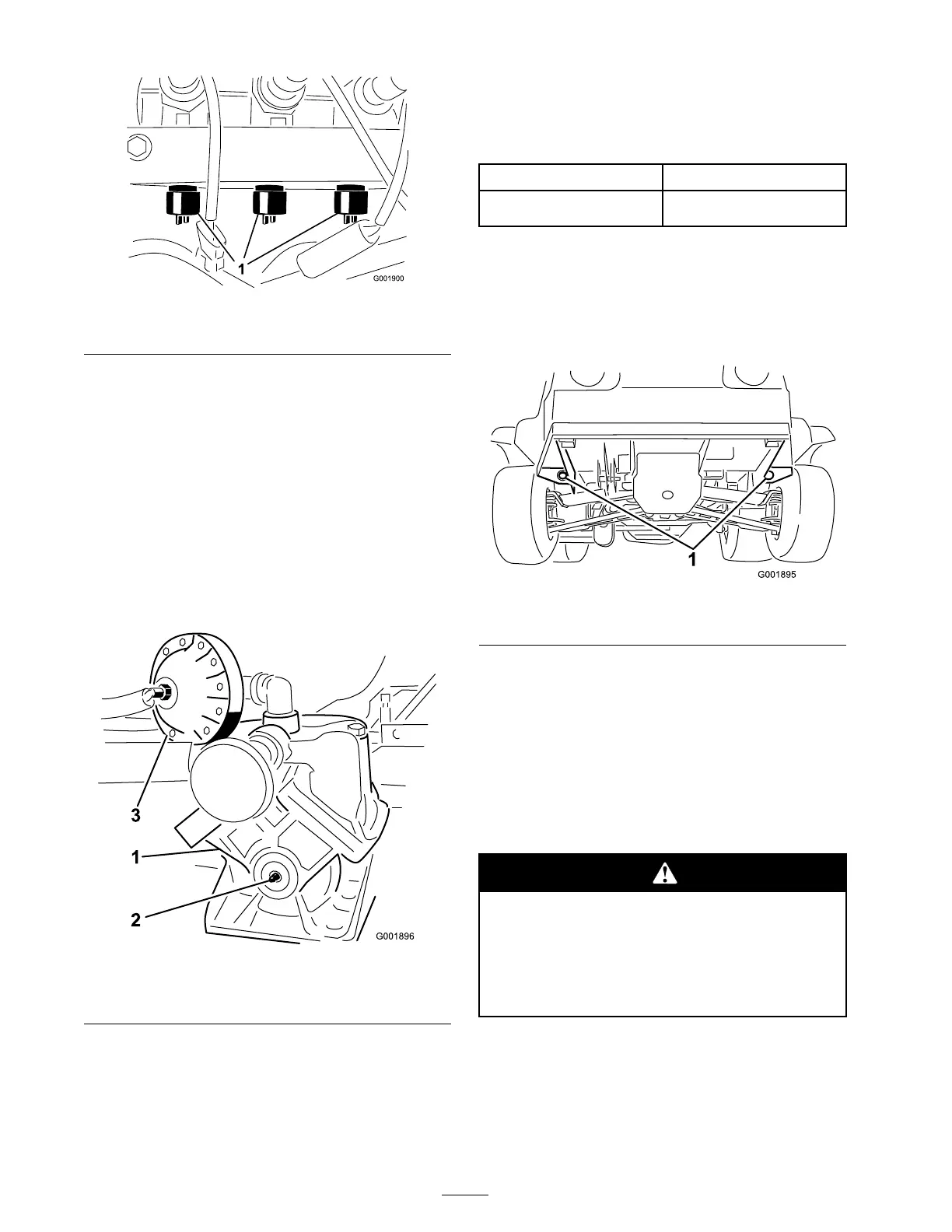
Transporting the Sprayer
F or mo ving the spra yer long distances , use a
trailer . Secure the spra yer to the trailer . Figure 32
illustrates the front tie-do wn points .
Figure 32
1. Tie down points
T he rear tie-do wn points are tw o steel loops under
the bac k of the frame just in front of the adjustable
boom frame .
Towing the Sprayer
In case of an emerg ency , the spra yer can be
to w ed for a shor t distance . Ho w ev er , w e do not
recommend this as a standard procedure .
T o wing at ex cessi v e speeds could cause a
loss of steering contr ol, r esulting in per sonal
injur y .
Nev er to w the spray er f aster than 5 mph
(8 kph).
T o wing the spra yer is a tw o person job . If
the mac hine m ust be mo v ed a considerable
distance , transpor t it on a tr uc k or trailer; refer to
T ranspor ting the Spra yer .
1. Affix a to w line to the frame .
36

 Loading...


