the actuator rod. If the actuator rod exhibits
mo v ement refer to belo w .
4. R e peat the procedure for the opposing boom.
If the actuator rod exhibits an axial mo v ement
(tra v els into or out of the cylinder) g reater than
0.085-0.100 inc h (2.16-2.54 mm), y ou ma y wish to
bleed the air from the h y draulic oil.
R efer to the Ser vice Manual for instr uctions on
ho w to bleed air from the actuators or contact an
A uthorized T oro Ser vice Distributor .
Emergency Manual
Operation of the Boom
Actuators
Note: Deter mine the left and right sides of the
mac hine from the nor mal operating position.
Use of the man ual r elief v alv e may cause the
boom to mo v e suddenl y and cause injur y to
y ou or other s.
• T ak e caution and adjust the man ual r elief
v alv e slo wl y .
• Ensur e the sur r ounding ar ea is clear and
no one is inside the operating range of
the boom.
Adjusting the man ual r elief v alv e with
electrical po w er pr esent could cause the
actuator operate ir r egular l y and cause injur y
to y ou or other s.
Do not use the man ual r elief v alv e while
electrical po w er is being supplied to the
actuator .
In case of an emerg ency suc h that the boom
m ust be mo v ed and no 12V DC po w er source is
a v ailable , the man ual relief v alv e can be used to
reliev e pressure within the actuator and allo w the
booms to be mo v ed man ually .
Important: T he man ual v alv e must not be
loosened mor e than 4 tur ns. T ur ning the v alv e
mor e than 4 tur ns may cause the v alv e to come
of f completel y allo wing h y draulic oil to spill
out.
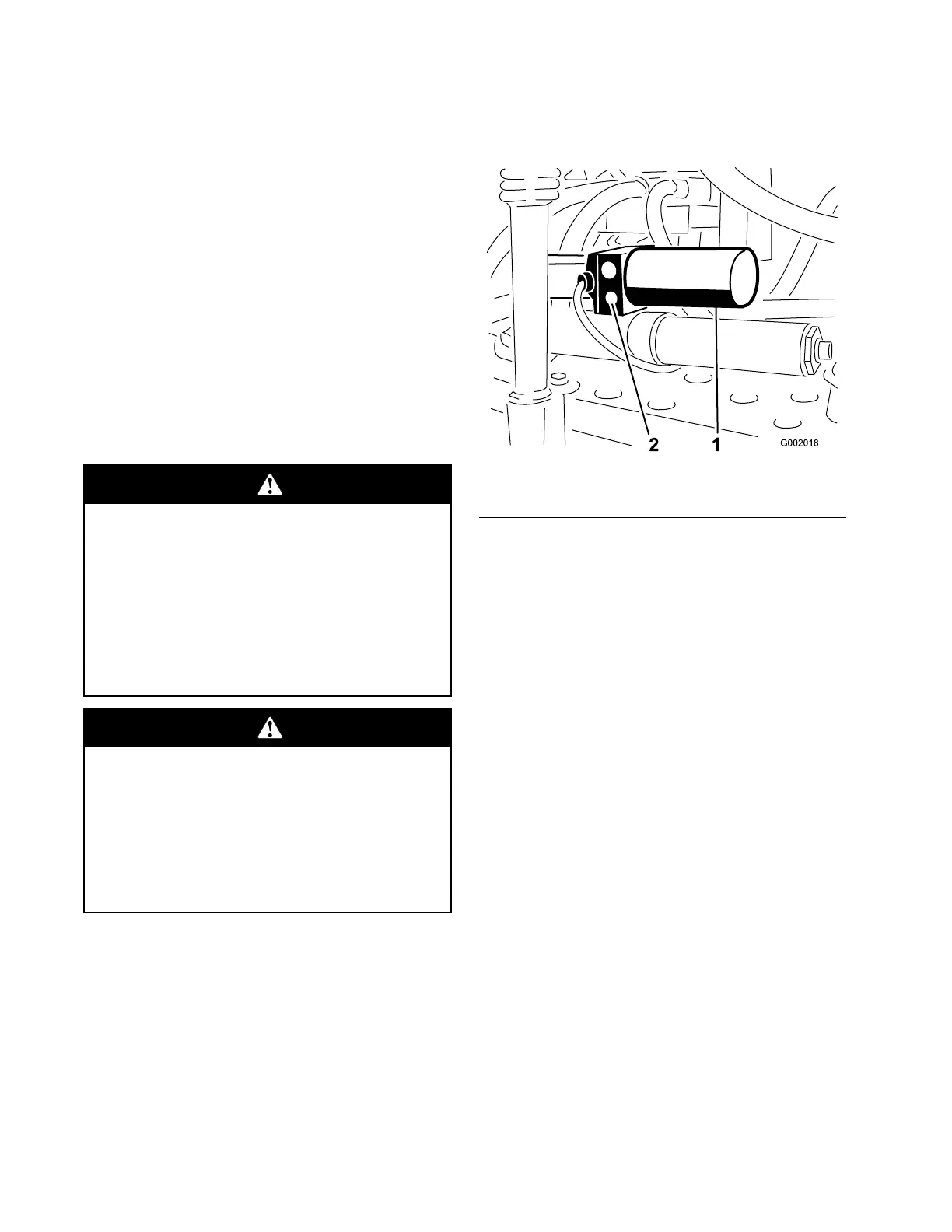
1. Locate the man ual relief v alv e on the actuator
for eac h boom. T he man ual relief v alv e is the
smaller v alv e and is only on one side of the
actuator body ( Figure 72 ).
Figure 72
1. Actuator, right boom 2. Manual relief valve
Note: Due to the opposing orientation of
actuators in respect to eac h other the man ual
relief v alv e is on the forw ard face of the left
boom actuator and the rear face of the right
boom actuator .
2. Use a hexag onal wrenc h to loosen the man ual
relief v alv e no mor e than 2-3 tur ns . T he
cylinder should star t stroking man ually or b y
exter nal pressure at this time .
3. Once the original position of the actuator
is reco v ered, close the man ual relief v alv e .
T or que the v alv e to 1.1-2.1 ft-lb (1.5-2.9 N ⋅ m).
Inspecting the Nylon Pivot
Bushings
Inspect the nylon pi v ot bushings in the center
boom ev er y 400 hours and/or yearly for damag e .
1. P osition the spra yer on a lev el surface , set the
parking brak e , stop the pump , stop the engine ,
and remo v e the ignition k ey .
2. Extend the booms to the spra y position and
suppor t the booms using stands or straps from
a lift.
3. With the w eight of the boom suppor ted,
remo v e the bolt and n ut securing the pi v ot pin
to the boom assembly ( Figure 73 ). R emo v e the
pi v ot pin.
58

 Loading...


