10
220VAC(OutsideUSandCanada)OutdoorModels
Step 1 – Route power and ground wires from a power source through a conduit and into the
EVOLUTION
®
cabinet.
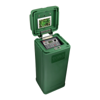
Step 2 – Open the EVOLUTION
®
controller and access the internal components.
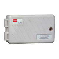
Step 3 – Remove the power compartment cover to access the transformer terminals.
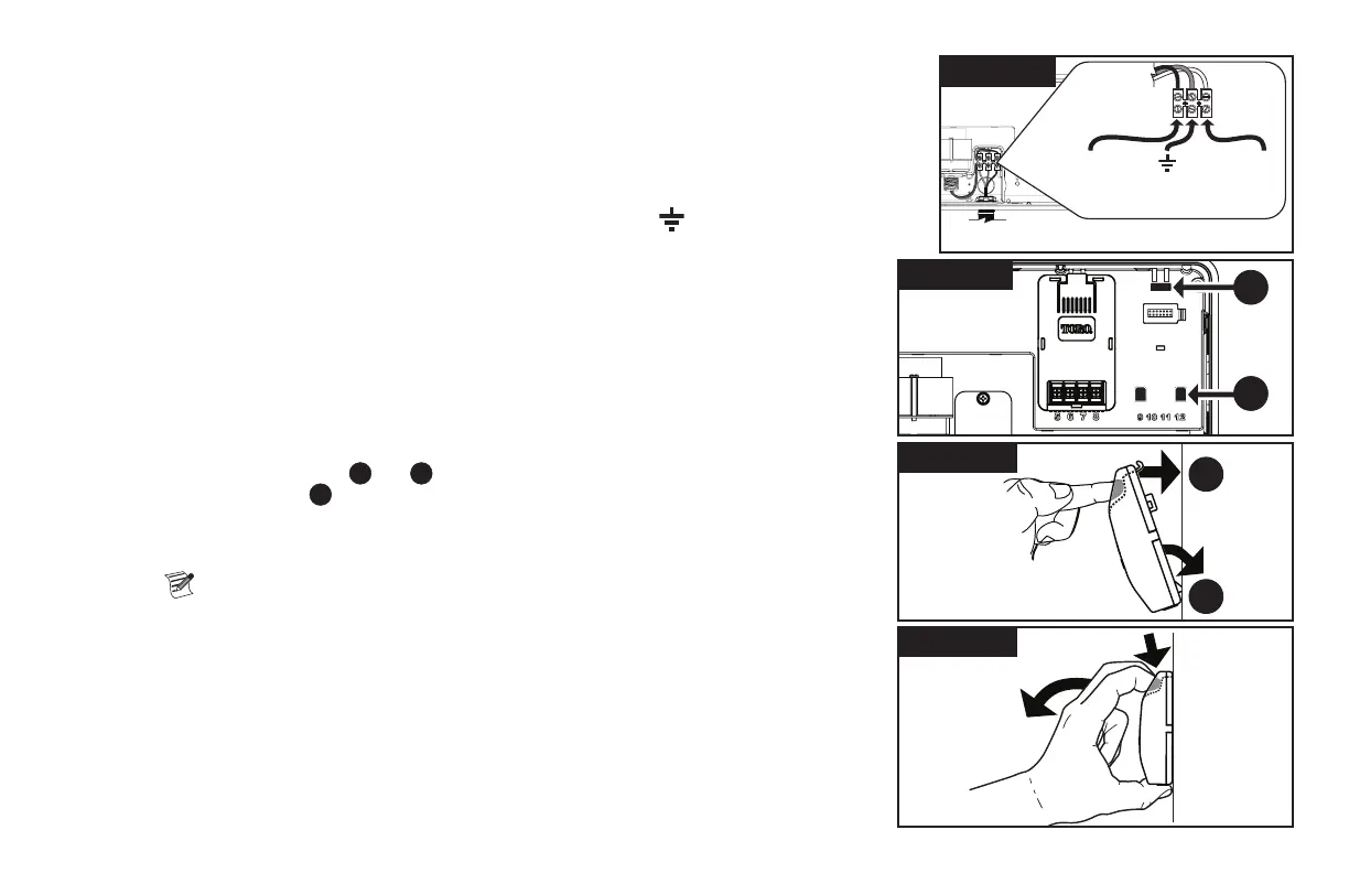
Step 4 – Remove1/2”(12.7mm)ofinsulationfromthepowersourcewireendsandinstallthebrownwire
intotheLine(L)terminal.InstallthegreenwireintotheGround( )terminalandthebluewire
intotheNeutral(N)terminal.
Step 5 – Install and secure the power compartment cover.
Step 6 – Apply power to the controller.
Zone Expansion Module Installation
The EVOLUTION
®
controllercanbeexpandedusingtheoptional4-zone(EMOD-4)or
12-zone(EMOD-12)modulestoaddmorezonestothesystem.
Module Installation
Step 1 – Open the EVOLUTION
®
controller door and control panel to access the internal
components.
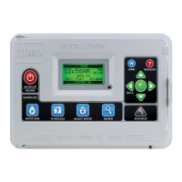
Step 2 – Locate the module slot
and
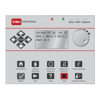
. Install the module by placing the bottom hooked
standosintoslot
and push the module tab towards the cabinet until a positive click is
achieved. The click indicates that the module’s retaining tab is fully engaged.
Once installed, the EVOLUTION
®
controller will be able to read the additional zones and will
make them available for scheduling.
Note: Ifinstallingonlyonefour-stationmodule(EMOD-4),itmustbeinstalledinthe
zone 5-8 module slot.
Module Removal
Step 1 – Open the EVOLUTION
®
controller door and control panel to access the internal
components.
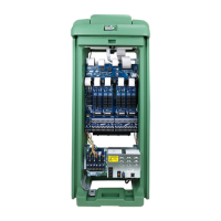
Step 2 – Hold the module as shown in Figure 11. Press the retaining tab while pulling the top of the
module away from the cabinet, then lift the module out of
the controller.
Brown
Blue
Green/Yellow
(L) (N)
( )
220 VAC Outdoor Models
Figure 8
Figure 11
Figure 9
B
A
Figure 10
B
A