9
Set the Beginning of the Week
Step 1 – Use the Down arrow to select BEGIN WEEK. Press the Right arrow or SELECT .
Step 2 – Use the Up or Down arrowstoselectSUNDAY(default)orMONDAYasthebeginningoftheweeklyschedule.
Press SELECT whennished.
Step 3 – Navigate to the next item or press the HOME button to return to the main screen if setup is complete.
Installation
Power Supply Installation
WARNING:ACpowerwiringmustbeinstalledandconnectedbyqualiedpersonnelonly.Allelectricalcomponentsandinstallationproceduresmust
comply with all applicable local and national electrical codes. Some codes may require a means of disconnecting from the AC power source installed in
thexedwiringandhavingacontactseparationofatleast0.120"(3mm)inthelineandneutralpoles.MakesurethepowersourceisOFFpriortoconnecting
thecontroller.Ifthesupplycordisdamaged,itmustbereplacedbythemanufacturer.itsserviceagentorasimilarlyqualiedpersoninordertoavoidahazard.
WARNING:Thisapplianceisnotintendedforusebypersons(includingchildren)withreducedphysicalsensory,ormentalcapabilities,orlackof
experience and knowledge, unless they have been given supervision or instruction concerning use of the appliance by a person responsible for their
safety. Children should be supervised to ensure that they do not play with the appliance.
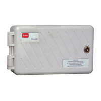
Indoor and 240 VAC Outdoor Models
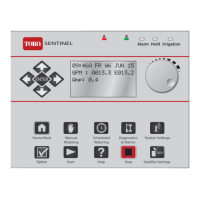
Indoor models and the 240 VAC Outdoor model will be pre-wired with a power cord ready to be plugged into
awallpowersocket(Figure 6).
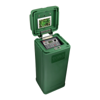
110VAC(USandCanada)OutdoorModels
Step 1 – Route power and ground wires from a power source through a conduit and into the
EVOLUTION
®
cabinet.
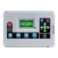
Step 2 – Open the EVOLUTION
®
controller and access the internal components.
Step 3 – Remove the power compartment cover to access the transformer wiring.
Remove1/2”(12.7mm)ofinsulationfromthewireends.
Step 4 – Usingtheprovidedwirenuts,securethetransformerLine(black)wire
totheblackpowersourcewire,Neutral(white)tothewhitepowersourcewireandEquipment
Groundwire(green)tothegreenpowersourcewire.
Note: Earlier EVOLUTION
®
modelisequippedwithtwoEquipmentGroundwires(green).
Connect both wires to the green power source wire.
Step 5 – Install and secure the power compartment cover.
Step 6 – Apply power to the controller.
Figure 6
Figure 7
Black White Green
110 VAC Outdoor Models