11
Battery Installation
The EVOLUTION
®
controller uses a 9-VDC battery for arm-chair programming.
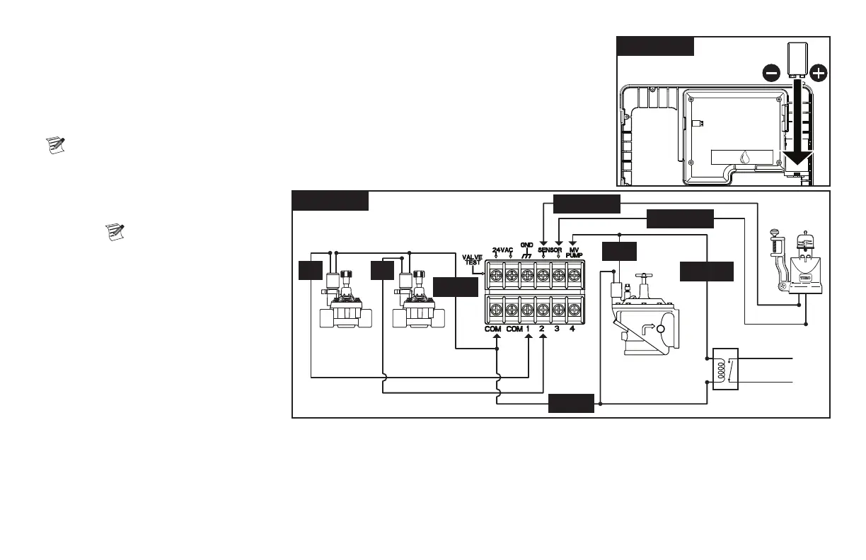
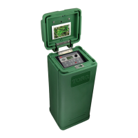
Step 1 – Open the EVOLUTION
®
controller door and control panel to access the
internal components.
Step 2 – Locate the battery compartment at the back of the control panel.
Step 3 – Alignthepolarity(–and+)ofthebatterythenslideitintothebatterycompartmentasshownin
Figure 12.
Note: You may need to pull the battery tab forward to align the battery properly.
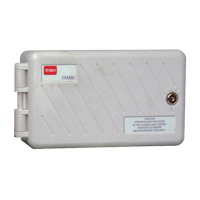
Valve, Pump Relay and Sensor Installation
Step 1 – Route valve wires from the valves,
master valves, pump relay and/or
sensor into the controller cabinet.
Note:18AWG(1.0mm2)
multi-wire sprinkler valve
connection cable can be used.
This cable is insulated for direct
burial and is color-coded to
simplify installation. It can be
routed directly into the controller
through the access hole provided
forvalvewireconduit(ifconduitis
notused).
Step 2 – Connect valves, master valves and
pump start relay to the valve wires
- Connect the white color-coded
wire from the cable to one wire
from each valve solenoid and/or
pumprelay.(Eitherofthetwowires
fromthesolenoidorpumprelaycanbeusedforthisconnection.)Thisconnectionwillbedesignatedasthevalvecommonwire.
Connect a separate cable wire to the remaining wire from each valve solenoid. Note the wire color-code used for each valve and the zone it
controls. You will need this information when connecting the valve wires to the controller.
Connect sensor to the valve wires - Connect any two unused color-coded wires to the sensor. Note the color-code of the sensor wires for
installation.
Step 3 – Secure all wire splices using wire nut connectors. To prevent corrosion and possible short circuits, always use an insulated wire nut, grease
caporsimilarwaterproongmethod.
Figure 12
Figure 13
1 2
MV
PUMP
SENSOR
SENSOR
COM
COM