3
© 2008 - 2011 TOSHIBA TEC CORPORATION All rights reserved e-STUDIO2020C/2330C/2820C/2830C/3520C/3530C/4520C
ADJUSTMENT
3 - 1
3. ADJUSTMENT
3.1 Image Related Adjustment
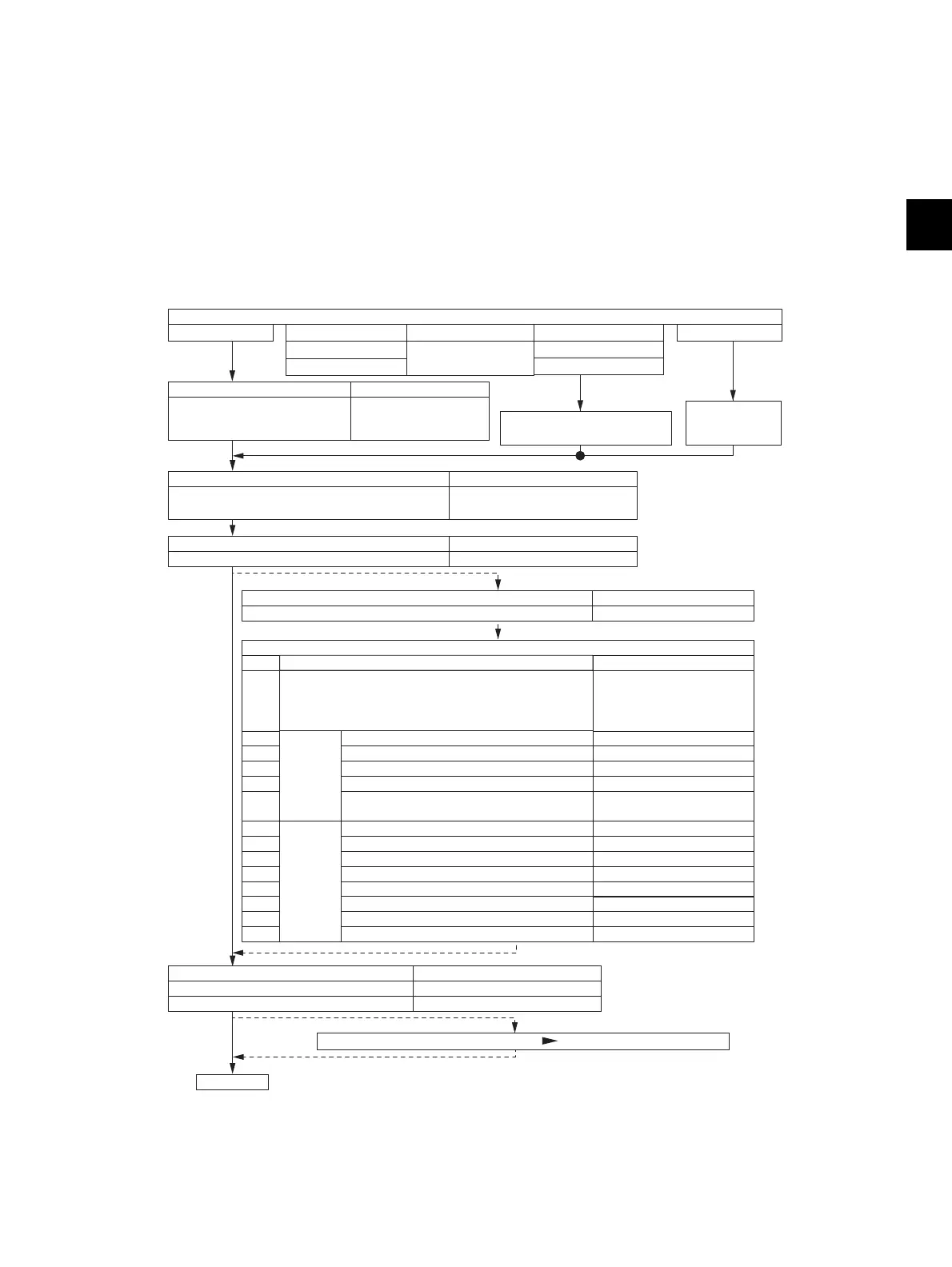
3.1.1 Adjustment Order
This chapter mainly explains the procedures for image related adjustment. When replacing
components which have other specified instructions for adjustment, those specified instructions are to
be obeyed in priority.
In the following diagram, the solid lines with arrow lead to essential adjustments, while the dotted lines
lead to adjustments to be performed if necessary.
Fig. 3-1
sensor(*2)
2
3
4
1
7
8
9
10
11
12
13
14
5
6
408, 440, 441, 444, 428, 442, 445
401
411
487
(a) Image distortion
(b) Reproduction ratio of primary scanning direction
(c) Image location of primary scanning direction
(d) Reproduction ratio of secondary scanning direction
(e) Image location of secondary scanning direction
(f) Top margin
(g) Right margin
(h) Bottom margin
–
405
306
340
305
430
432
433
498
(b) Primary scanning data laser writing start position
(c) Reproduction ratio of secondary scanning direction
(a) Reproduction ratio of primary scanning direction
(d) Secondary scanning data laser writing start position
(e) Primary scanning data laser writing start position at
duplexing
4100, 4101, 4103, 4104, 4105,
4106, 4107, 4108, 4109, 4110,
4111, 4115, 4116, 4117, 4118,
4120, 4122, 4123, 4124, 4125,
4126, 4127, 4128, 4129
396(*4)
Item to be adjusted
3.1.3 Adjustment of image quality control /
Automatic initialization of image quality control
Code in mode 05
Item to be adjusted Code in mode 05
3.1.2 Adjustment of the auto-toner
Developer material
Image quality sensor(*1)
Needle electrode
Transfer belt(*1)
Image position aligning
sensor(*1)
Drum cleaning blade
Laser optical unit
1st transfer roller(*1)
Main charger grid
Photoconductive drum
3.1.6 Image dimensional adjustment
Items
Code in mode 05
3.1.7 .Paper alignment at the registration roller
Order
3.1.9
3.1.8
Image
dimensional
adjustment
at the
printing
section
Image
dimensional
adjustment
at the
scanning
section
Adjust the image quality if necessary.
(
Chapter 3.1, 3.2, 3.3, 3.4, 3.5
)
END
Code in mode 05
1642(*5), (1644, 580)
1008(*6), 1004 - 0, 1004 - 2 to 8
Item to be adjusted
3.2.1 Automatic gamma adjustment
(
PPC
)
3.3.1 Automatic gamma adjustment
(
PRT
)
Parts to be replaced
Item to be adjusted Code in mode 05
3.1.4 Adjustment of color registration control 4719
Item to be adjusted Code in mode 05
3.1.5 Adjustment of the transfer belt due to environmental factors 408
*1: There is no need to perform counter clear.
*2: Adjust only the color changed.
*3: When the SRAM board <LGC board> has been replaced, perform the adjustment from 05-4721.
*4: When upgrading firmware, perform the adjustment from 05-396.
*5: Use [4] + [FAX] test pattern.
*6: Use [70] + [FAX] test pattern.
200(Y,M,C,K), 201(Yellow)
202(Magenta), 203(Cyan)
204(Black), 206(Y
,M,C)
Life counter clear
([6]+[START]: PM support mode)
T
ilt motor initial
excitation setting
(05-4721) (*3)
 Loading...