12
© 2013-2017 TOSHIBA TEC CORPORATION All rights reserved
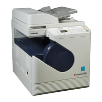
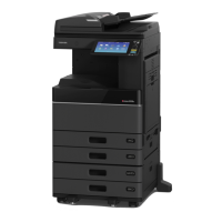
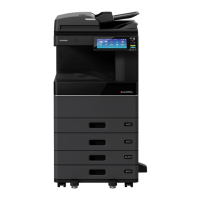
e-STUDIO2006/2306/2506/2007/2307/2507/2303A/2303AM/2803AM/2309A/2809A
EXTERNAL COUNTERS
12 - 1
12. EXTERNAL COUNTERS
12.1 Outline
This specification describes the interface between external counters, such as Coin Controller and Card
Counter.
12.2 Signal
12.2.1 Pin Layout <20L/23L/25L/20H/23H/25H>
1. Connector on the MAIN board: CN35 (Coin Controller)
Pin
No.
I/O
Signal
name
Function Voltage level Port Remarks GQ-1131
1 Power 24VCOV-
OFF
24V line DC24V±10% When cover
opened: OFF
In use
2 Out CTRON Total Counter On
Signal
Open Collector OPAL
PL0
L: ON In use
3 In KCTRC Counter Connection
Signal
L=0V, H=DC5V OPAL
PL5
L: Connected
Connected to SG
with harness
In use
4 Out MCRUN Ready to Copy
Signal
Open Collector OPAL
PM4
L: Operating In use
5 Out EXTCTR Exit Sensor On
Signal
Open Collector OPAL
PM3
L: ON In use
6 GND PG Power ground 0V In use
7- - - - - - -
8- - - - - - -
9 GND SG Signal ground 0V In use
10 - - - - - - -
11 - - - - - - -
12 - - - - - - -
13 - - - - - - -
14 Power 5V 5V line DC5.1V±3% In use
15 In CTRON-EN Counter enabled
signal
L=0V, H=DC5V OPAL
PJ6
L: Enabled In use
16 Out L/S-SIZE Paper size (large/
small) signal
Open Collector OPAL
PM6
L: Large size
H: Small size
In use
 Loading...