13 - 10
Motors Sensors and switches
Electromagnetic clutches
PC boards
Lamps and heaters
Thermistors and thermostats
Others
Symbol Name Figure
Wire harness
location
M1
SCAN-MOT
Scan motor
[A]
M2
TNR-MOT
Ton e r mo t or
[C]
M3
MAIN-MOT
Main motor
[E]
M4
M/DC-POL
Polygonal motor
[C]
M5
SUC-FAN-MOT
Suction fan
[D]
M6
EXIT-MOT
Exit motor
[C]
M7
ADU-FAN
ADU fan (Option)
[H]
Symbol Name Figure
Wire harness
location
S1
TEMP/HUMI-SNR
Temperature/humidity sensor
[E]
S2
RGST-SNR
Registration sensor
[E]
S3
EXIT-SNR
Exit sensor
[C]
S4
ATTNR-SNR
Auto-toner sensor
[D]
S5
EMP-SNR
Paper empty sensor
[G]
S6
SFB-SNR
Bypass paper sensor
[F]
S7
PLTN-SNR
Platen sensor
[A]
S8
ADU-TR-SNR
ADU sensor (Option)
[H]
S9
APS-R
Automatic original detection sensor
[A]
SW1
MAIN-SW
Main switch
[B]
SW2
SIDE-COV-INTLCK-SW
Right cover opening/closing interlock switch
[B]
SW3
SIDE-COV-INTLCK-SW
Right cover opening/closing interlock switch
[B]
SW4
FRNT-COV-INTLCK-SW
Toner supply cover opening/closing interlock
switch
[B]
Symbol Name Figure
Wire harness
location
CLT1
RGST-CLT
Registration roller clutch
[E]
CLT2
CST-L-FEED-CLT
Drawer feed clutch
[E]
CLT3
SFB-CLT
Bypass feed clutch
[H]
CLT4
ADU-CLT
ADU clutch (Option)
[H]
Symbol Name Figure
Wire harness
location
MAIN
PWA-F-MAIN
Main PC board (MAIN board)
[E]
CTIF
PWA-F-LDRS
Laser driving PC board (LDRS board)
[C]
CTRG
PWA-F-CTRG
Toner cartridge PC board (CTRG board)
[C]
FUS
PWA-F-FUS
Fuse PC board (FUS board)
[D]
HPNL
PWA-F-HPNL
Control panel PC board (HPNL board)
[A]
LDR
PWA-F-LDRS
Laser driving PC board (LDRS board)
[C]
Symbol Name Figure
Wire harness
location
DH1
DRM-DH
Drum damp heater
[D]
ERS
LP-ERS
Discharge LED
[D]
LAMP1
HTR-LAMP
Heater lamp
[C]
LAMP2
SIDE-LAMP
Side heater lamp
[C]
Symbol Name Figure
Wire harness
location
THMO1
THRMO-FSR-C
Fuser center thermostat
[C]
THMO2
THRMO-FSR-F
Fuser front thermostat
[C]
THMS1
THMS-C-HTR
Center thermistor
[C]
THMS2
THMS-S-HTR
Side thermistor
[C]
THMS3
THMS-EDG-HTR
Edge thermistor
[C]
THMS4
THMS-DRM
Drum thermistor
[D]
Symbol Name Figure
Wire harness
location
CIS
CIS
Contact image sensor unit
[A]
HVPS
PS-HVT
High-voltage transformer
[B]
LVPS
PS-ACC
Switching regulator
[B]
[A] Scanner unit, control panel [B] Power supply, developer unit [C] Laser unit, fuser unit, toner cartridge [D] Drive unit
CIS
HPNL
LCD
M1
S9S10
S7
SW3
SW2
SW4
SW1
LVPS
HVPS
CTRG
M2
CTIF
THMS3
M4
S3
LDRS
THMO1
THMO2
THMS1
LAMP2
THMS2
LAMP1
M5
ERS
THMO3
FUS
DH1
S4
THMS4
[E] Automatic duplexing unit, transfer unit, exit unit [F] Bypass feed unit [G] Drawer unit [H] Automatic duplexing unit, transfer unit, exit unit
CLT2
M3
MAIN
S2
CLT1
S1
S6
S5
M7
M6
CLT3
S8
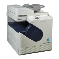
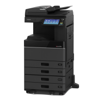
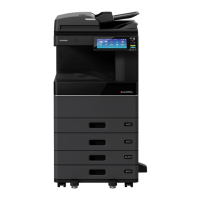
13.10 Electric Parts Layout <23HA/28HA>
 Loading...