194 GX9 ASD Installation and Operation Manual
AM Output Terminal Function
Program Terminal Analog Output Terminals
This setting determines the output function of the AM analog output terminal.
The AM output terminal produces an output voltage or current that is
proportional to the magnitude of the function assigned to this terminal. The
available assignments for this output terminal are listed in Table 9 on pg. 221.
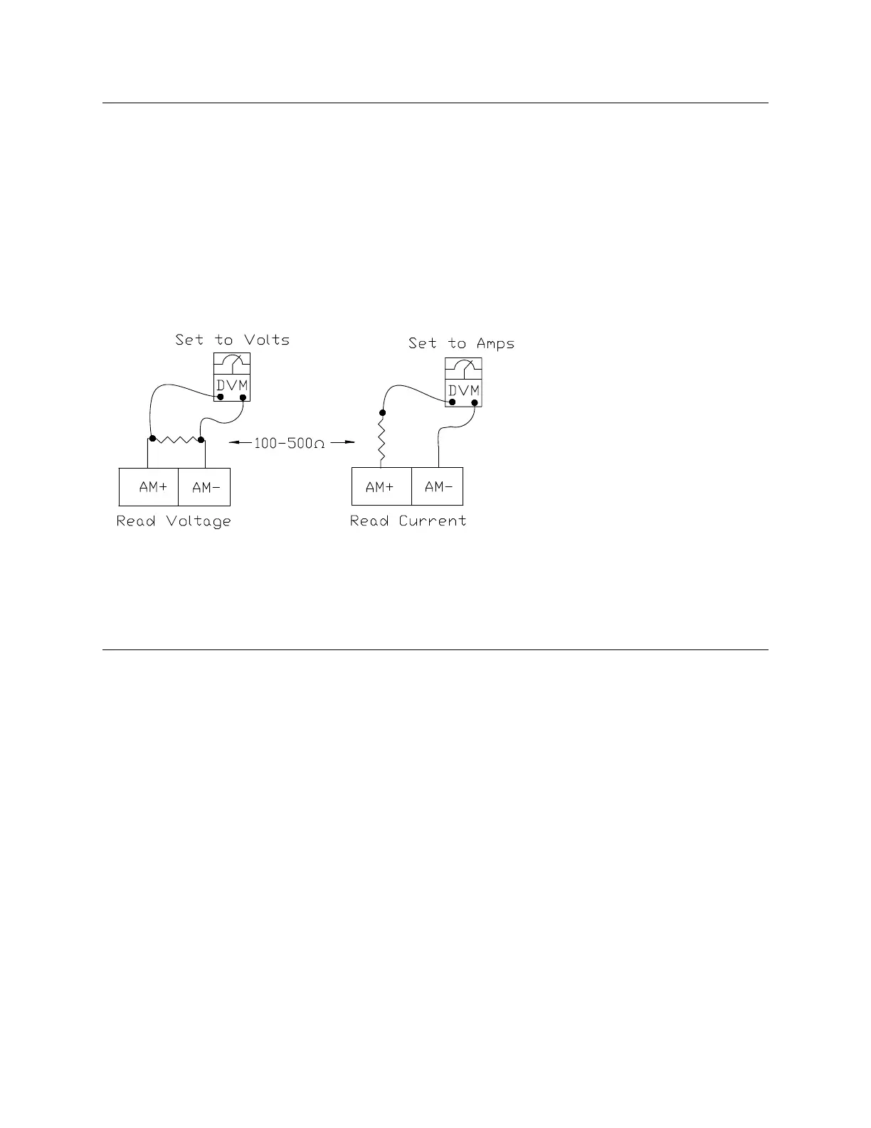
To read voltage at this terminal, connect a 100 – 500 resistor from AM (+) to
AM (-). The voltage is read across the 100 – 500 resistor.
To read current at this terminal, connect a 100 – 500 resistor in series from
AM (+), through the current meter, to AM (-).
The AM Output Terminal Adjustment (F671) is used to calibrate the output
signal for a proper response. SW-2 at the Terminal Board may be switched to
allow for the full-range output to be either 0 – 1 mA or 4 – 20 mA when
providing an output current, or either 0 – 1 or 1 – 7.5 volts when providing an
output voltage at this terminal.
Direct Access Number — F670
Parameter Type — Selection List
Factory Default — Output Current
Changeable During Run — Yes
AM Output Terminal Adjustment
Program Terminal Analog Output Terminals
This parameter is used to calibrate the AM terminal analog output.
To calibrate the AM analog output, connect a meter (current or voltage) as
described at F670.
With the ASD running at a known value (e.g., output frequency), adjust this
parameter until the assigned function produces the desired DC level output at
the FM output terminal.
See F670 for more information on this setting.
Direct Access Number — F671
Parameter Type — Numerical
Factory Default — 512
Changeable During Run — Yes
Minimum — 1
Maximum — 1280
F670 F671
 Loading...


