218 GX9 ASD Installation and Operation Manual
32 33
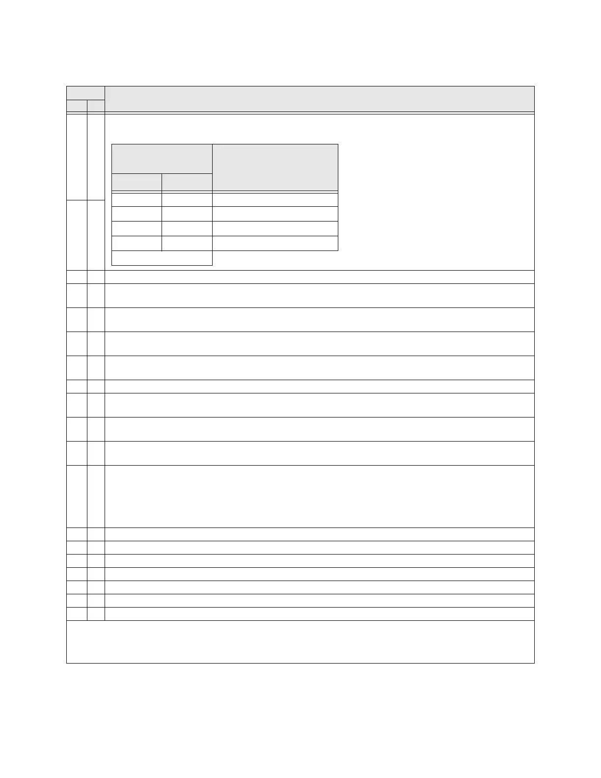
Torque Limit 1/2 Switching/Torque Limit 3/4 Switching — Activating combinations of discrete input terminals
Torque Limit Switching allow for the selection of a torque limit switching profile as listed below.
34 35
36 37 PID Off — Activation turns off PID control.
38 39
Pattern Run Selection 1 — Activation selects the configured Pattern 1 Pattern Run for operation. Deactivate to
remove the configured Pattern 1 Pattern Run.
40 41
Pattern Run Selection 2 — Activation selects the configured Pattern 2 Pattern Run for operation. Deactivate to
remove the configured Pattern 2 Pattern Run.
42 43
Pattern Run Selection 3 — Activation selects the configured Pattern 3 Pattern Run for operation. Deactivate to
remove the configured Pattern 3 Pattern Run.
44 45
Pattern Run Selection 4 — Activation selects the configured Pattern 4 Pattern Run for operation. Deactivate to
remove the configured Pattern 4 Pattern Run.
46 47 Pattern Run Continuation — Initiates a continuation of the last Pattern Run from its stopping point.
48 49
Pattern Run Trigger — Initiates the first Preset Speed of a Pattern Run and initiates each subsequent enabled
Preset Speed with continued activations.
50 51
Forced Jog Forward — Provides a forward-run signal for the duration of the activation (the status of the F and R
terminals is ignored). Use F260 to set the Jog Run Frequency and use F261 to select the Jog Stop Method.
52 53
Forced Jog Reverse — Provides a reverse run signal for the duration of the activation (the status of the F and R
terminals is ignored). Use F260 to set the Jog Run Frequency and use F261 to select the Jog Stop Method.
54 55
Binary Bit 0 — Bit 0 – 7 may be set up as a speed/torque control register. Speed/torque settings may be applied to
this group of terminals in binary form. The required number of input terminals should be set to the respective
binary bit settings (0 – MSB). The Frequency Mode setting must be set to
Binary/BCD.
The gain and bias of the binary input may be set from the following path: Program
Frequency
Speed
Reference Setpoints
BIN (see F228).
56 57 Binary Bit 1 — Used in conjunction with terminal setting 54/55 above.
58 59 Binary Bit 2 — Used in conjunction with terminal setting 54/55 above.
60 61 Binary Bit 3 — Used in conjunction with terminal setting 54/55 above.
62 63 Binary Bit 4 — Used in conjunction with terminal setting 54/55 above.
64 65 Binary Bit 5 — Used in conjunction with terminal setting 54/55 above.
66 67 Binary Bit 6 — Used in conjunction with terminal setting 54/55 above.
68 69 Binary Bit 7 — Used in conjunction with terminal setting 54/55 above.
Note: NO/NC = Normally Open/Normally Closed.
Note: Selection numbers are used when configuring the ASD via communications. They differentiate the Normally
Open and Normally Closed contact settings.
Table 8. (Continued) Discrete Input Terminal Assignment Selections and Descriptions.
Sel. No.
Terminal Selection Descriptions
NO NC
Torque Limit
Switching Terminal
Torque Limit Selection
#1 #2
00 1
01 2
10 3
11 4
1=Terminal Activated
The 1 – 4 settings of the torque limit switching
selections are performed at parameters F440 –
F449.
 Loading...


