GX9 ASD Installation and Operation Manual 217
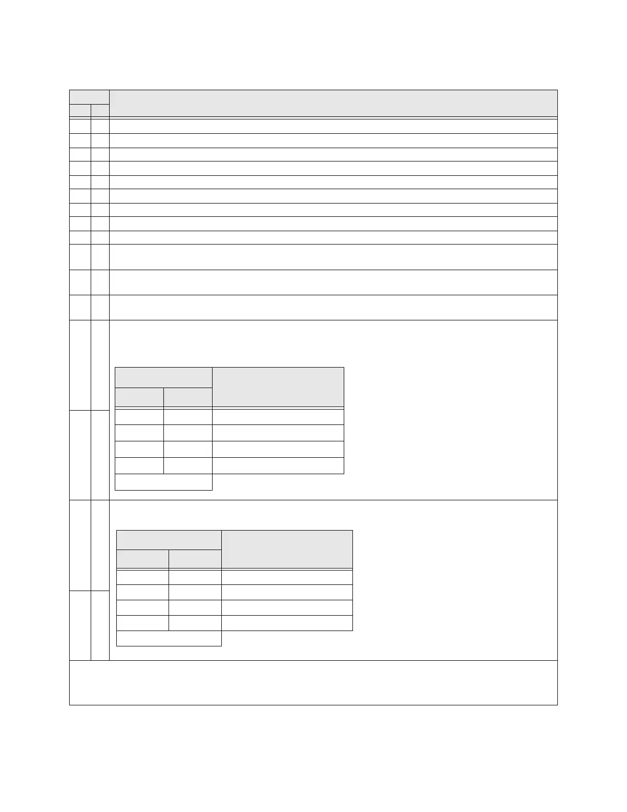
Table 8. Discrete Input Terminal Assignment Selections and Descriptions.
Sel. No.
Terminal Selection Descriptions
NO NC
01
Unassigned — No operation.
23Forward — Provides a Forward run command.
45Reverse — Provides a Reverse run command.
67Standby — Enables the Forward and Reverse operation commands.
89Reset — Resets the device and any active faults.
10 11 Preset Speed 1 — Preset Speed 1 is used as the LSB of the 4-bit nibble that is used to select a Preset Speed.
12 13 Preset Speed 2 — Preset Speed 2 is used as the second bit of the 4-bit nibble that is used to select a Preset Speed.
14 15 Preset Speed 3 — Preset Speed 3 is used as the third bit of the 4-bit nibble that is used to select a Preset Speed.
16 17 Preset Speed 4 — Preset Speed 4 is used as the MSB of the 4-bit nibble that is used to select a Preset Speed.
18 19
Jog Setup Terminal — This terminal activates a Jog for the duration of the activation. The Jog settings may be
configured at F260 and F261.
20 21
Emergency Off — Terminates the output signal from the ASD and may apply a brake if so configured. The braking
method may be selected at F603.
22 23
Forced DC Braking — The ASD outputs a DC current that is injected into the windings of the motor to quickly
brake the motor.
24 25
Accel/Decel 1/2 Switching/Accel/Decel 3/4 Switching — Activating combinations of discrete input terminals
Accel/Decel Switching allow for the selection of an Accel/Decel profiles 1 – 4 as shown below.
See F504 for more information on this terminal setting.
26 27
28 29
Motor 1/2 Switching/Motor 3/4 Switching — Activating combinations of discrete input terminals Motor
Switching allow for the selection of a V/f switching profile as shown below.
30 31
Note: NO/NC = Normally Open/Normally Closed.
Note: Selection numbers are used when configuring the ASD via communications. They differentiate the Normally
Open and Normally Closed contact settings.
A/D SW Terminal
A/D Profile Selection
#1 #2
00 1
01 2
10 3
11 4
1=Terminal Activated
The settings of the A/D selections 1 – 4 are performed
at F009/F010, F500/F501, F510/F511, and F514/
F515, respectively.
Accel/Decel profiles are comprised of the Accel/
Decel settings, Pattern, and Switching Frequency.
V/f Switching Terminal
V/f Selection
#1 #2
00 1
01 2
10 3
11 4
1=Terminal Activated
The 1 – 4 settings of the V/f Switching
selections are performed at parameters F170 –
F181.
 Loading...


