EasyManua.ls Logo

Toshiba TH650A - 1 Specifications; Name of each Part

Toshiba TH650A
72 pages
To Next Page IconTo Next Page
To Previous Page IconTo Previous Page
Loading...
TRANSPORTATION AND INSTALLATION MANUAL
1. Specifications
1.1 Name of Each Part
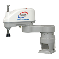
Fig. 1.1 shows the name of each part of the robot.
Fig. 1.1 Name of each part
Battery box
Ball screw spline
(tool sh
aft)
Arm 2
Arm 1
Cover
Base
Axis 2
(rotation)
Axis 1
(rotation)
Axis 4
(rotation)
Axis 3 (vertical
movement)
Motor drive cable
connector (CN5)
Two spares
(grommet)
Quick-operated joint
for 6 mm
-dia. tube
Control signal
cable connector
(CN4)
Encoder cable
connector (CN3)
Tool flange
Eyebolt
Brake OFF switch
D-SUB panel
Cannon panel
(option)
Brake OFF switch
Spare (grommet)
Spare (grommet)
D-SUB connector
Cannon connector
4×M5
Air joint for
hand
4×M5
Air joint for
hand
STE 85305
10

Table of Contents

Other manuals for Toshiba TH650A

Related product manuals