TRANSPORTATION AND INSTALLATION MANUAL
4. System Connections
4.1 Cable Wiring
This section describes the various types of cables and connectors and explains how
these are to be connected.
4.1.1 Connector Arrangement on the Controller
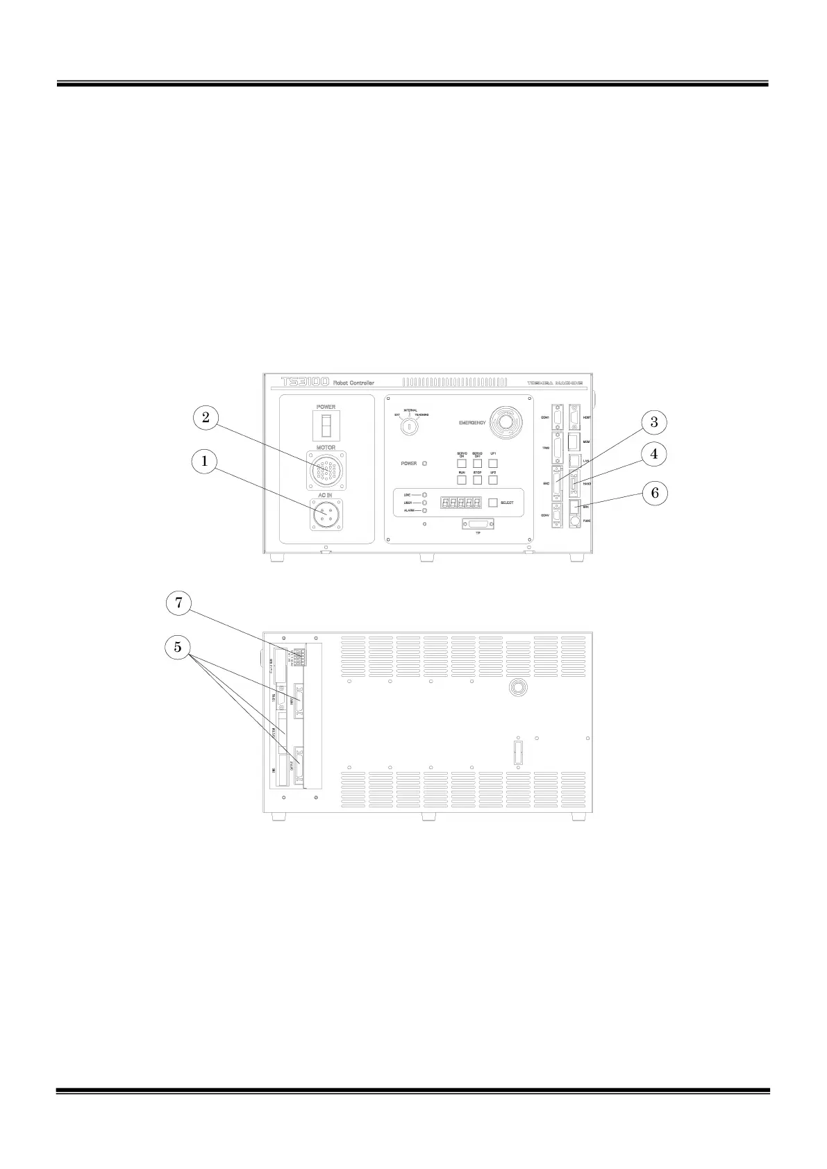
The cables connected to the robot controller are shown in Fig. 4.1.
Fig. 4.1 Robot controller connector arrangement
Power cable (ACIN)
Motor cable (MOTOR)
Encoder cable (ENC)
Robot control signal cable (HAND)
External operation input signal cables (SYSTEM, INPUT, OUTPUT)
Brake signal cable (BRK)
Distribution I/O cable (EXT-I/O)
STE 85305
– 33 –

 Loading...


