TRANSPORTATION AND INSTALLATION MANUAL
In the subsequent paragraphs, we explain how to connect cables to inclusive.
For information on how to connect cables , and , refer to the Interface Manual.
4.1.2 Connecting the Power Cable “CN1”
([1] of Fig. 4.1; plug connector attached)
The power cable is used to supply the main AC power to the controller.
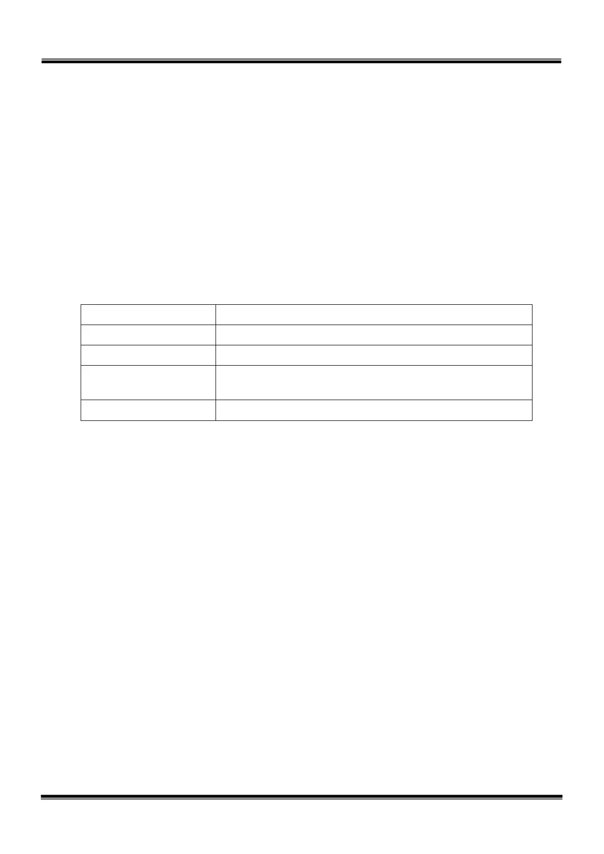
Table 4.1 Power supply specifications
Item Specifications
Power supply Single phase, AC 200 ~ 240 V, 50/60 Hz ±1 Hz
Power capacity 3.5 kVA
Instantaneous power
failure
Within 40 msec
Grounding
Grounding with grounding resistance of 100 Ω or less
The connector is ACIN ( of Fig. 4.1).
ACIN plug connector Type:
JL04V–6A22-22SE-EB-R
Maker: Japan Aviation
Electronics Industry
ACIN cable clamp Type: JL04–2022CK (14)-R Maker: Japan Aviation
Electronics Industry
Wire 3.5 mm
~ 5.5 mm
As the cable is not an accessory, use the attached plug connector connected to ACIN
on the controller side to manufacture a cable.
Wires are to be soldered to the connector.
STE 85305
– 34 –

 Loading...


