TRANSPORTATION AND INSTALLATION MANUAL
5.2 Tool Wiring and Piping
The robot is provided with wiring and air piping for the tool. These wiring and piping
extend to the arm 2 and are used as follows:
5.2.1 Tool Signals (Controller Side)
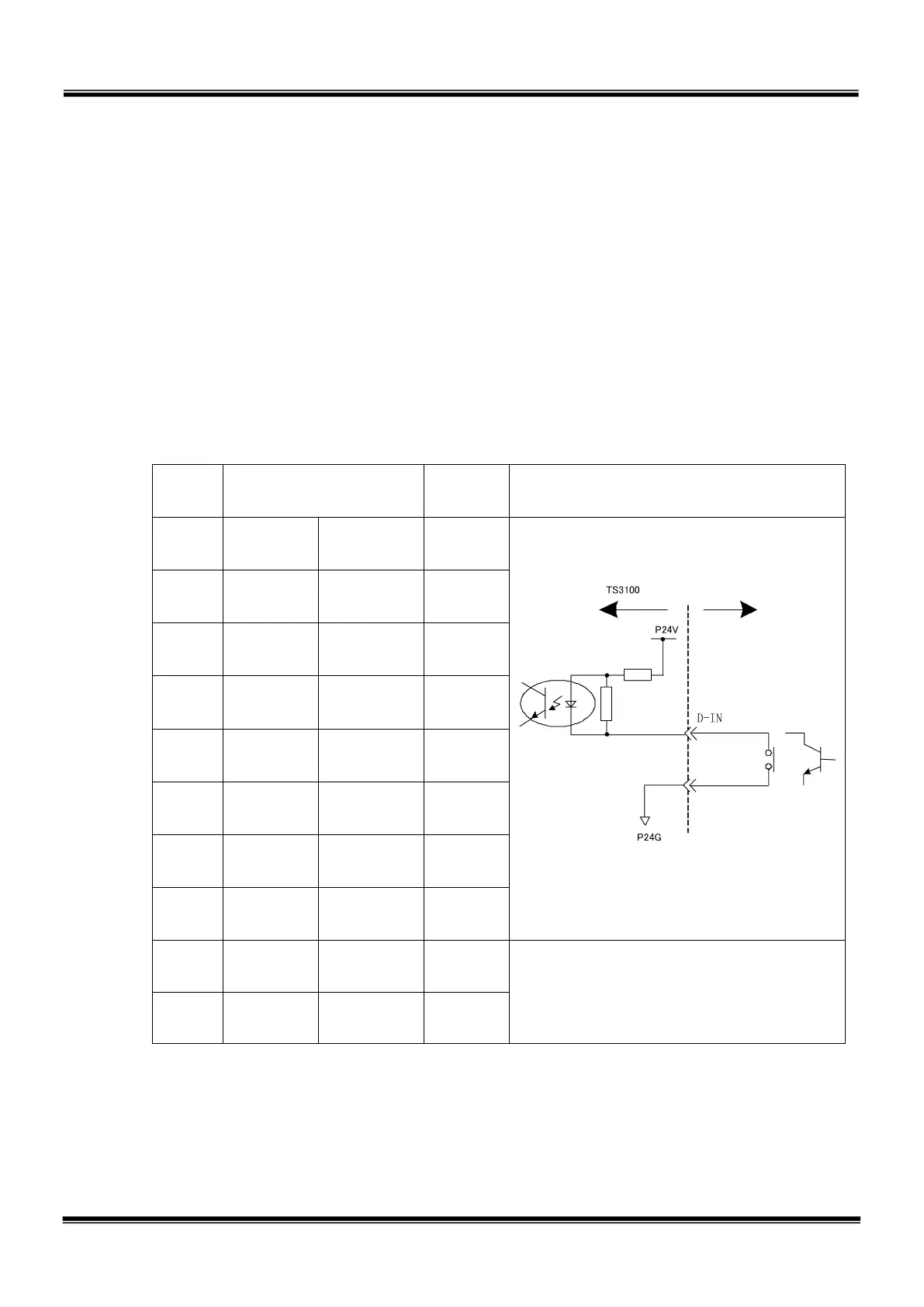
The controller is provided with the tool signals of eight input signals for sensors, eight
control signals for solenoid valves, DC24 V (P24V) signal, and DC24 V GND (P24G)
signal. The signals enable connection from the controller to external equipment.
a-1) Input signal connector HAND (Type-N)
Pin Signal name
Signal
No.
Input circuit and example of
connections
1 D-IN0
Input
signal 0
201
2 D-IN1
Input
signal 1
202
3 D-IN2
Input
signal 2
203
4 D-IN3
Input
signal 3
204
5 D-IN4
Input
signal 4
205
6 D-IN5
Input
signal 5
206
7 D-IN6
Input
signal 6
207
8 D-IN7
Input
signal 7
208
19 P24G 0 V
20
− −
’s side
STE 85305
– 49 –

 Loading...


