TRANSPORTATION AND INSTALLATION MANUAL
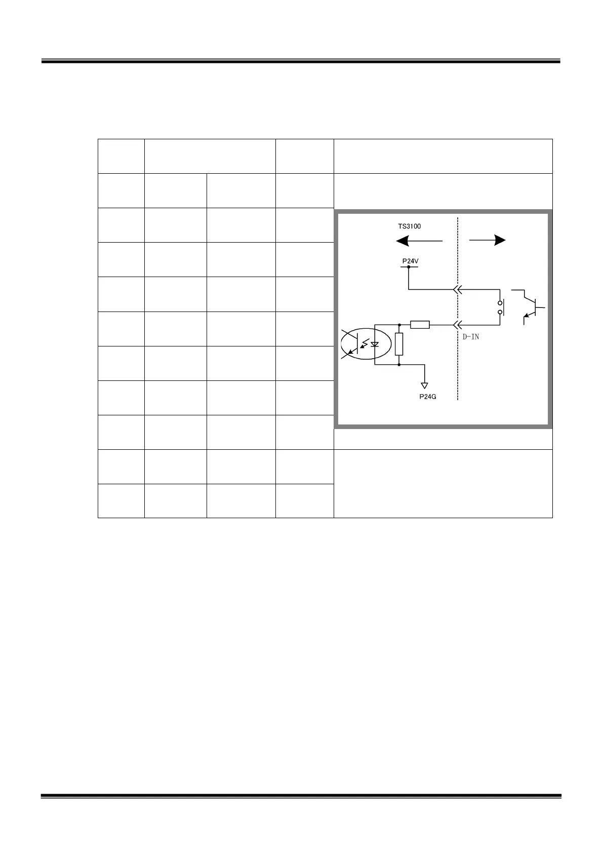
a-2) Input signal connector HAND (Type-P)
Pin Signal name
Signal
No.
Input circuit and example of
connections
1 D-IN0
Input
signal 0
201
2 D-IN1
Input
signal 1
202
3 D-IN2
Input
signal 2
203
4 D-IN3
Input
signal 3
204
5 D-IN4
Input
signal 4
205
6 D-IN5
Input
signal 5
206
7 D-IN6
Input
signal 6
207
8 D-IN7
Input
signal 7
208
19 P24V
DC24 V
power
20
− −
As input signals, no-voltage contacts or transistor open collector inputs are used.
No-voltage contact specifications:
Contact rating: DC24 V, 10 mA or over (circuit current: approx. 7 mA)
Minimum contact current: DC24 V, 1 mA
Contact impedance: 100 Ω or less
Transistor specifications:
Withhold voltage between collector and emitter: 30 V or over
Current between collector and emitter: 10 mA or over (circuit current: approx.
7 mA)
Leak current between collector and emitter: 100 µA or less
’s side
STE 85305
– 50 –

 Loading...


