TRANSPORTATION AND INSTALLATION MANUAL
b) As the cable connectors are connected to the rear side of the controller, provide
a space of 110 mm on the rear side.
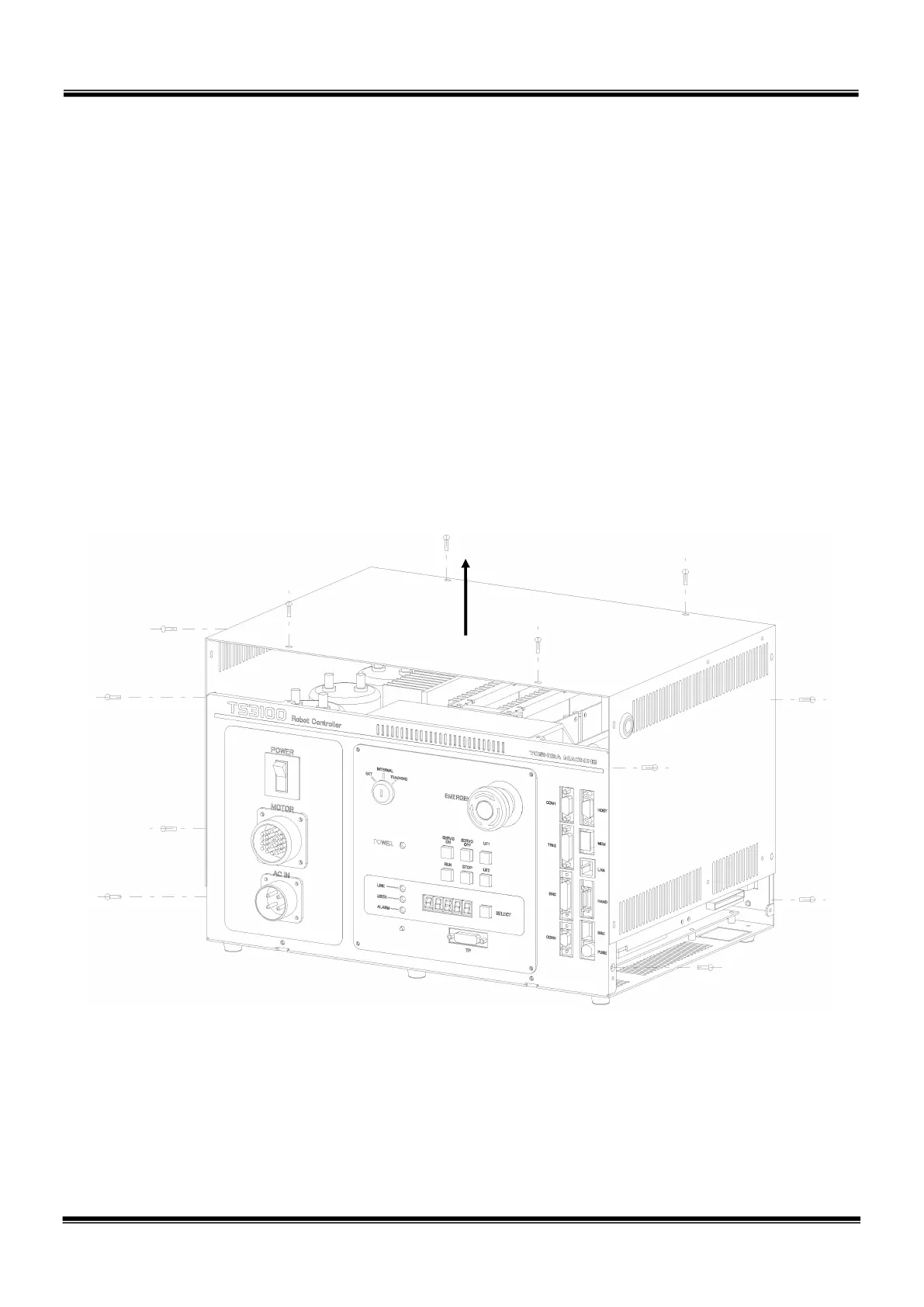
For maintenance, the upper cover should be removed. (See Fig. 3.8.)
Keep this in mind when installing the controller. At maintenance, the controller
should be removed from the rack. Specifically, be careful of the following
points.
1) Arrange the cables around the rear side of the controller (so that the
controller can be removed).
2) Arrange the cables between the controller and control panel when the
control panel is separated.
3) Connect all cables in such a manner that the robot can be operated even if
the controller is removed from the rack.
Fig. 3.8 Removing upper cover
STE 85305
– 30 –

 Loading...


