Apendix 1 100M-Ethernet Control LAN Network Configuration
126
z
Network Restrictions
Though the 100M-Ethernet control LAN is compliant with the IEEE802.3u specification, it is
subject to restrictions as the TOSDIC-CIE DS system. Thus, configure the network system
according to the following restrictions.
(1)
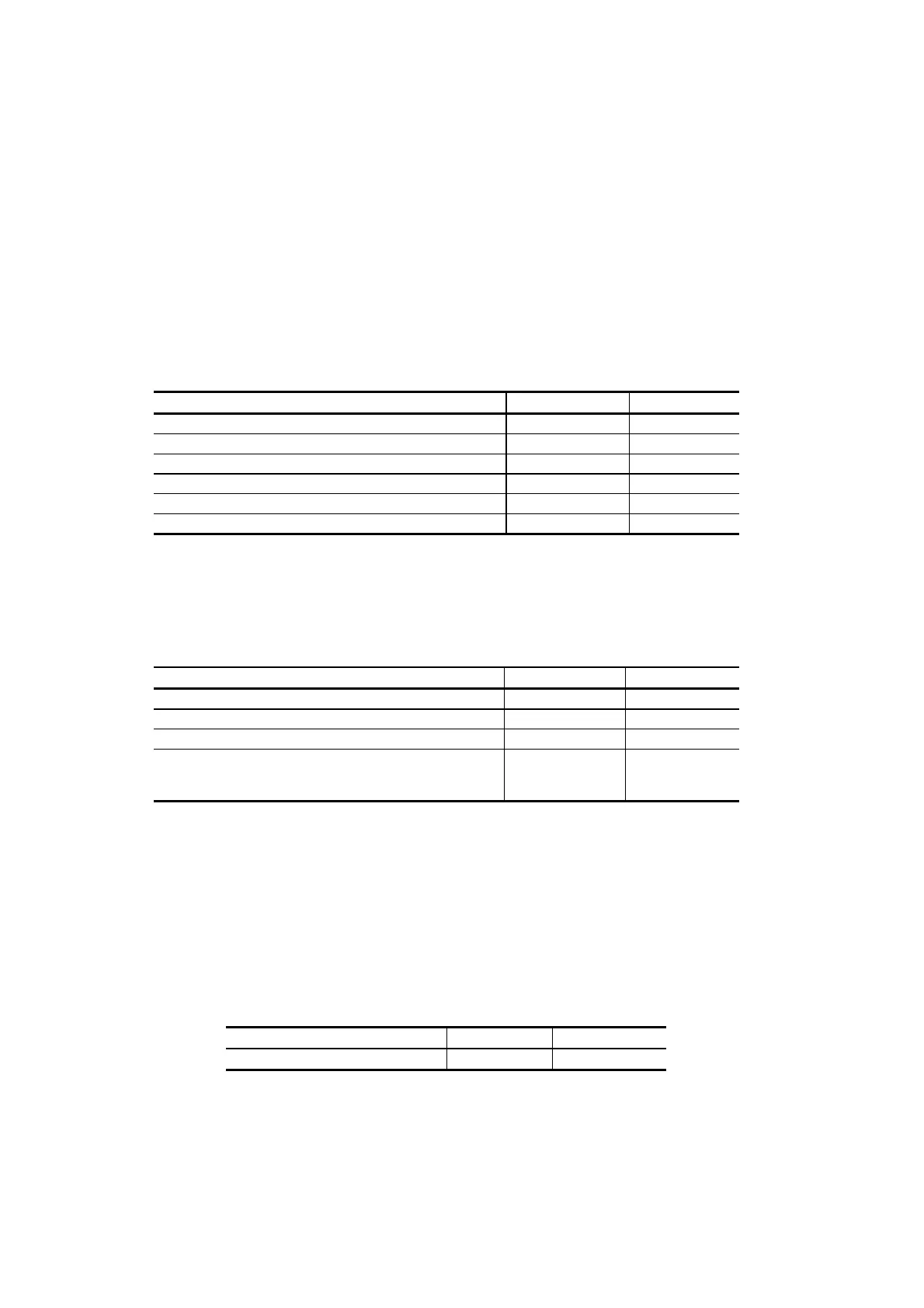
The lengths of twisted pair cables should be as shown in the table below.
Table A.4 Twisted Pair Cable Length
Maximum Length Remarks
Between switching hub and station 30 m See Figure A.4
Between hub and station 30 m See Figure A.4
Between switching hub and hub 30 m See Figure A.5
Between FX-TX conversion module and station 30 m See Figure A.6
Between FX-TX conversion module and switching hub 3 m See Figure A.6
Between FX-TX conversion module and hub 3 m See Figure A.8
(2)
The lengths of optical fiber cords/cables should be as shown in the table below.
Table A.5 0ptical Fiber Cords/Cables Length
Maximum Length Remarks
Between switching hub and switching hub 2 km See Figure A.6
Between switching hub and station 2 km See Figure A.7
Between switching hub and hub 150 m See Figure A.8
Between hub and station 150 m See Figure A.9
Applicable to
only one station
(3)
The number of switching hub stages is limited to a maximum of 2. (See Figure A.10)
By taking into account the delay time in the switching hub, the TOSDIC-CIE DS system
limits the number of switching hub stages to 2 to secure a response time between the OIS and
PCS. Therefore, the maximum transmission distance between two stations is as shown in
Table A.6
Table A.6 Transmission Distance
10M-Ethernet 100M-Ethernet
Maximum transmission distance 2.5km 8.0km
 Loading...


