2. Wiring of PCS-DS51
27
z
Cautions on installing Ethernet transmission lines
When installing Ethernet cables, be careful with the following.
Connection type of the item to be used
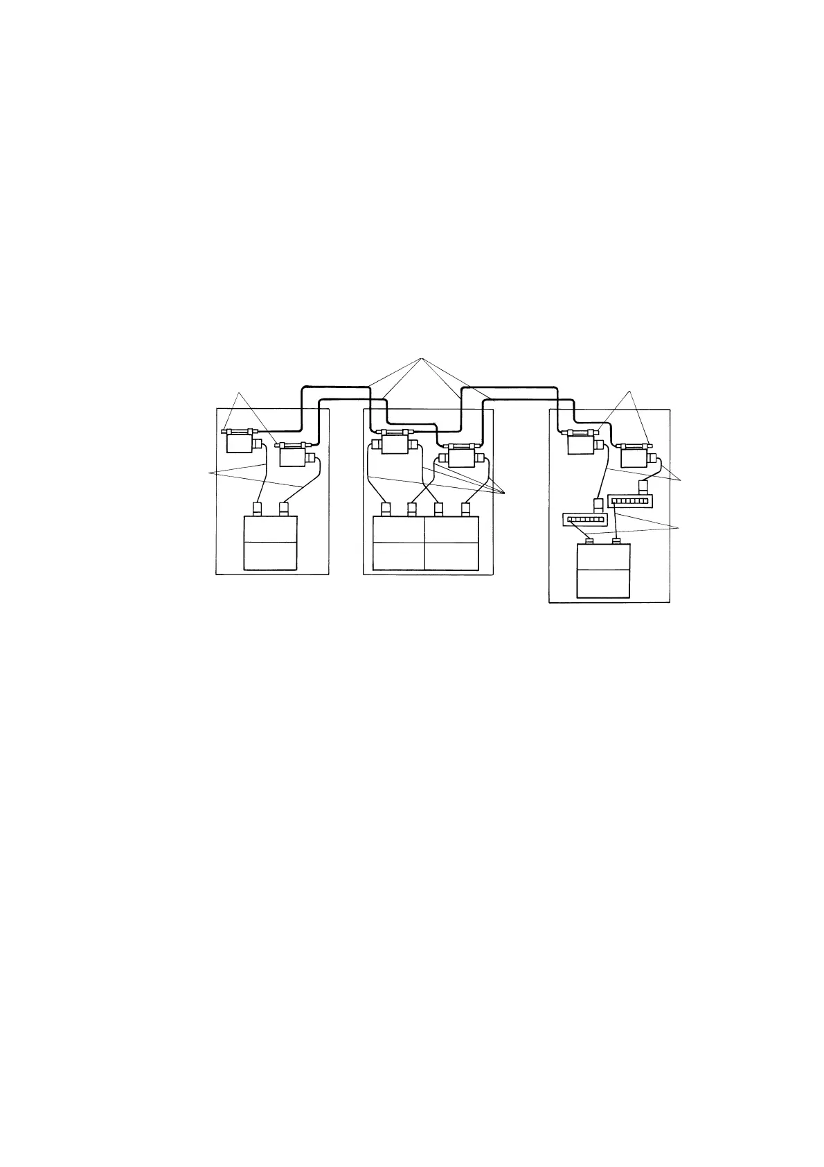
Figure 2.10 is an example of connection of items that make up the Ethernet transmission system.
Install a cable clamp to the D-sub connector of each PCS-DS51 main processor unit.
Ethernet-
board FETH1
PCS-DS
Main board
AUT cable
10BASE-T
twisted pair
cable
10BASE5 coaxial cable
Terminator
AUT
cable
AUT cable
Ethernet-
board FETH1
PCS-DS
Main board
Ethernet-
board FETH1
PCS-DS
Main board
Ethernet-
board FETH1
OIS-DS
Main board
TR
TR
MTR
TR
TR
MTR
Terminator
HUB
HUB
Figure 2.10 Connection Example of Ethernet Transmission Line
Usage standard of cables
Typically, the main processor unit and transceiver of PCS-DS51 are wired by using AUI cables.
10BASE5 coaxial cables are used for connections between PCS-DS51 cabinets in the same
building, as well as between operator rooms. 10BASE5 coaxial cable connects the transceivers,
and it cannot be directly connected to the main processor module or Ethernet board.
For the wiring route of 10BASE5 coaxial cables, refer to “External Wiring”.
Use optical cables for cable wiring between different buildings. When optical cables are used, an
optical repeater converts the electric signal to optical signal, and vise versa.
 Loading...


