2. Wiring of PCS-DS51
70
Wiring of Process Signal Cable
For the external signal cable connected to the terminal board unit, a typical instrumentation cable
can be used. The specifications of multi-wire cables used for the analog signal cable are as
follow.
Twisted cable with instrumentation batch shield
AWG size : For process I/O card #18 ∼
#20
For terminal board connection #16 ∼
#20
INSTRUCTION:
For multi-wire cables, do not use analog signals and digital signals together.
Weak analog input signal of 200mV or less should not exist together with other level signals.
Table 2.10 lists the types of terminal board units and the PI/O modules that correspond to the
terminal board units.
For the external wiring of the PI/O module and the signal table of the terminal board unit, refer to
“Appendix 1 PI/O Module/Communication Base Unit/Terminal Board Unit”.
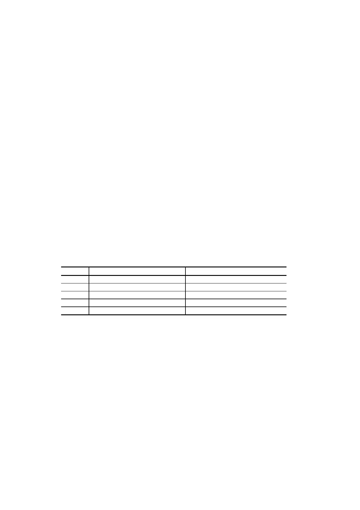
Table 2.10 Terminal Board Unit
Type Usage Applicable Modules
UTBA1 For 8-point analog/4-point pulse I/O SAI01,STC01,SAO01,SPI01,SPO01
UTBA2 For 4-point analog SAI02,SAI03,SRT01,SAO02
UTBA3 For 8-point no-insulating distributor SAI01 and SDA01(used in pairs)
UTBD1 For digital I/O SDI01,SDO01
UTRC1 For I/O relay connection SDI01,SDO01
Each terminal board unit may be used as described below.
•
UTBA1 to UTBA 3 with the option board attached to them can convert between current and
voltage.
•
One unit of the PI/O module can be installed to UTBD1.
Two units of the PI/O module can be installed to other terminal board units.
•
UTRC1 is specifically for the I/O relay unit (Omron), and its external line is connected with
the flat cable.
•
UTBA3 is specifically for SAI01 and SDA1.
 Loading...


