2. Wiring of PCS-DS51
56
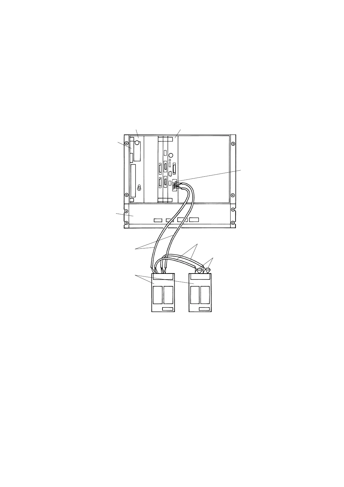
Wiring of Serial Bus Cable
The serial bus cable sends the process I/O data between the PCS-DS51 main unit and serial PI/O
system. In this section, the main processor card and communication base unit are connected with
the serial bus cable.
Serial bus cable
Communication
base unit
Terminating resistor
(Note 1)
Power supply card Main processor card
Main unit
Fan unit
Serial bus cable
Terminating
resistor
Figure 2.35 Wiring of Serial Bus Cable
z
Configuration of Communication Base Unit
For the serial PI/O system in the standard system extended configuration, up to 15 units of
communication base unit which are all connected to one serial bus. To one unit of communication
base unit, the terminal board unit can be connected via the I/O bus cable (see Figure 2.36).
The maximum configuration for the hardware is as follow.
 Loading...


