2. Wiring of PCS-DS51
63
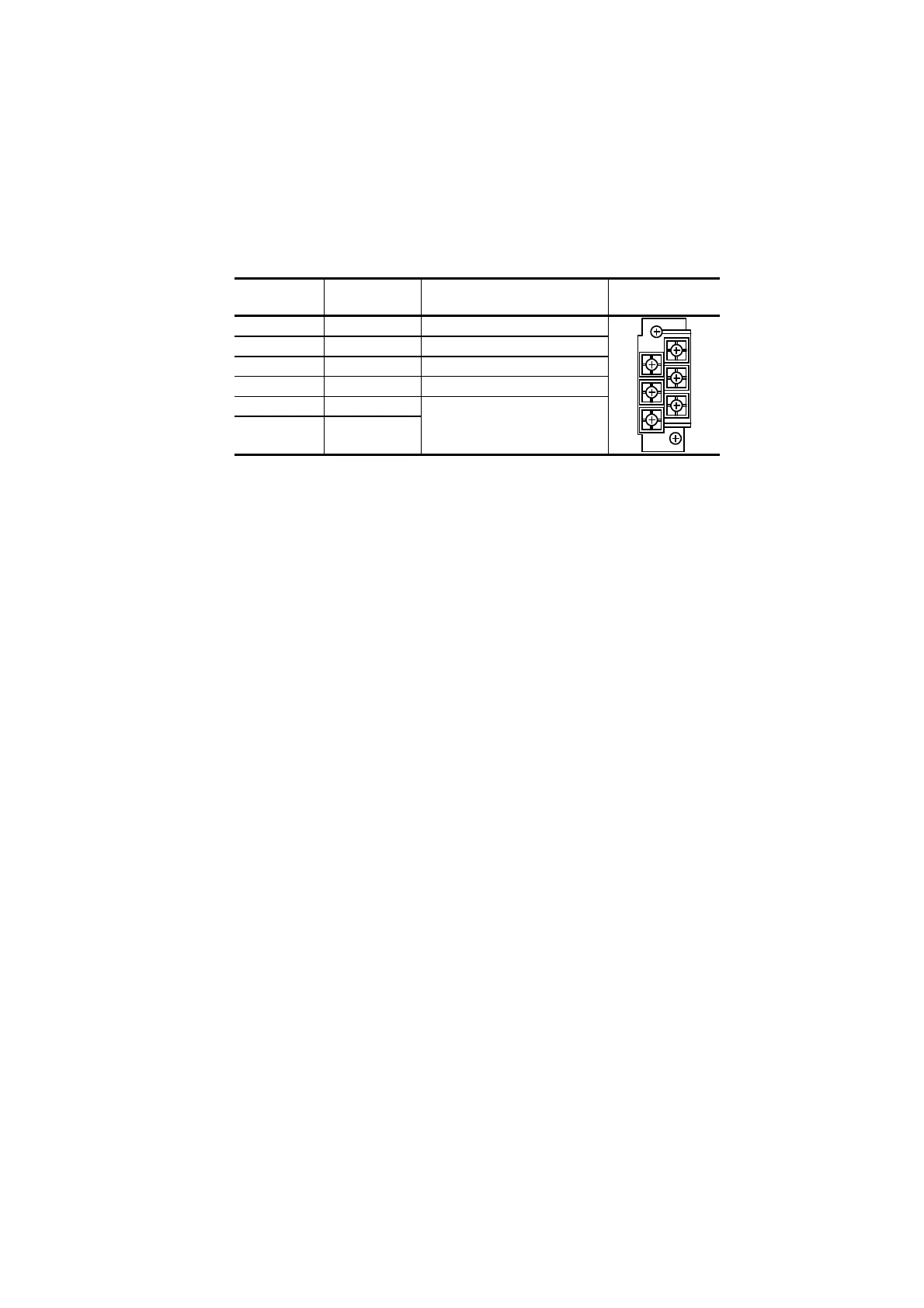
Table 2.9 is the signal list for the serial bus I/O terminal board.
Table 2.9 Serial Bus I/O Terminal Board
Terminal
No.
Signal Name Description
Schematic
Representation
1 LINE-A1 Serial bus A system(+)
2 LINE-B1 Serial bus B system(+)
3 LINE-A2 Serial bus A system(-)
4 LINE-B2 Serial bus B system(-)
5 SHIELD1 Shield of serial bus cable
6 SHIELD2 (common)
1
3
5
2
4
6
(Note) 1. To the terminal No.1 and 3, as well as 2 and 4, the terminating
resistors are connected.
2. For redundant configuration, the terminating resistor is usually
connected to the FMCS1 module of the primary side.
 Loading...


