E6581595
L-3
12
<Continued>
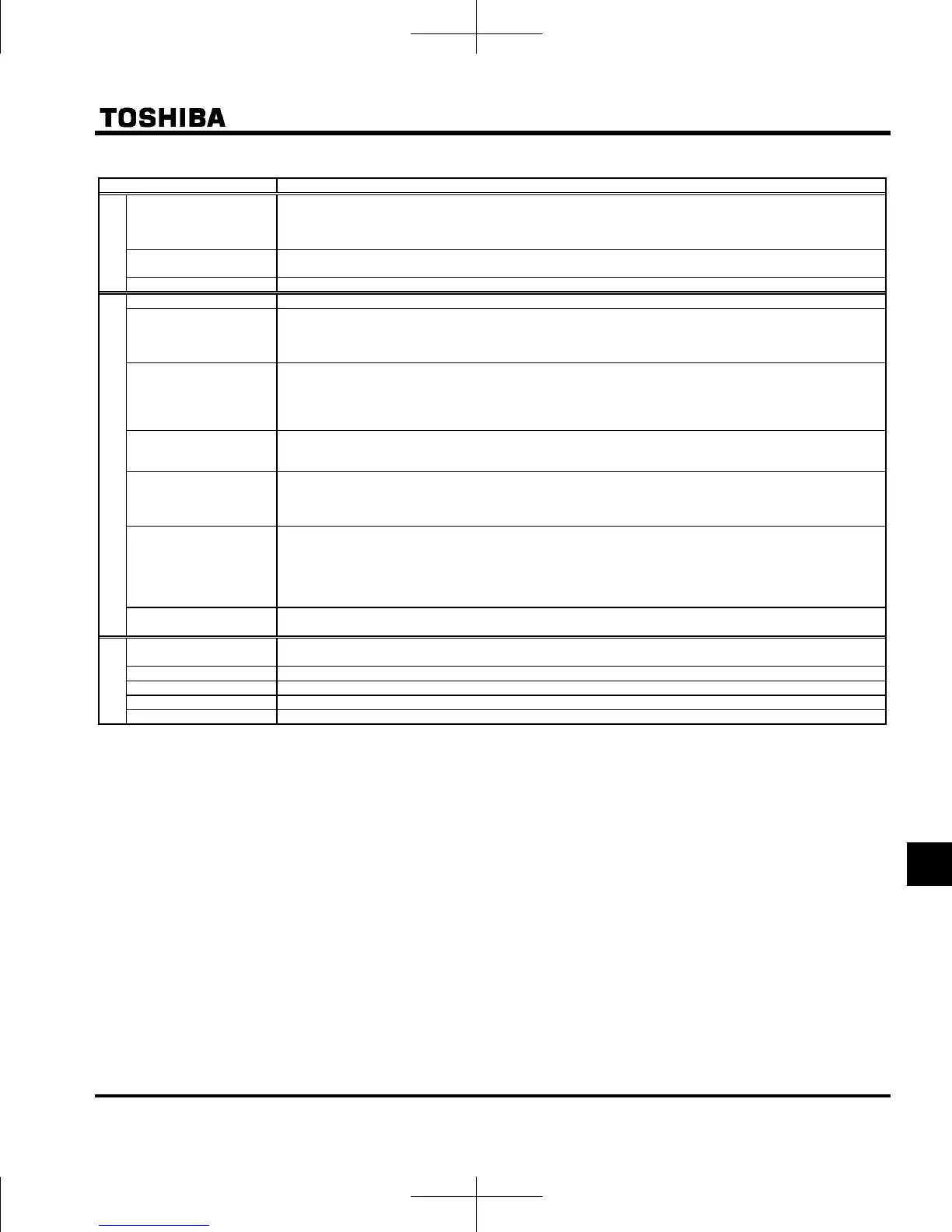
Item Specification
Protective
function
Protective function Stall prevention, current limitation, over-current, output short circuit, over-voltage, over-voltage limitation,
undervoltage, ground fault detection, input phase failure, output phase failure, overload protection by electronic
thermal function, armature over-current at start-up, load side over-current at start-up, over-torque, undercurrent,
overheating, cumulative operation time, life alarm, emergency stop, various pre-alarms
Electronic thermal
characteristic
Switching between standard motor and constant-torque VF motor, switching between motors 1 & 2, setting of
overload trip time, adjustment of stall prevention levels 1 & 2, selection of overload stall
Reset function Panel reset / External signal reset / Power supply reset. This function is also used to save and clear trip records.
Display function
Alarms Stall prevention, overvoltage, overload, under-voltage, setting error, retry in process, upper/lower limits
Causes of failures Over-current, overvoltage, overheat, output short-circuit, ground fault, overload on inverter, arm overcurrent at start-
up, overcurrent on the load side at start-up, CPU fault, EEPROM fault, RAM fault, ROM fault, communication error.
(Selectable: emergency stop, under-voltage, small current, over-torque, motor overload, input phase failure, output
phase failure)
Monitoring function Output frequency, frequency command value, forward/reverse run, output current, input voltage (DC detection),
output voltage, torque, torque current, load factor of inverter, input power, output power, information on input
terminals, information on output terminals, logic input terminals setting, version of CPU1, version of CPU2, PID
feedback value, frequency command (after compensation), causes of past trips 1to 4, parts replacement alarm,
cumulative operation time
Past trip monitoring
function
Stores data on the past four trips: number of trips that occurred in succession, output frequency, frequency
command value, forward/reverse run, output current, input voltage (DC detection), output voltage, information on
input terminals, information on output terminals, and cumulative operation time when each trip occurred.
Output for frequency
meter
Analog output for meter: 1mA dc full-scale dc ammeter
0 - 20mA (4 to 20mA) output: DC ammeter (allowable load resistance: Less than 750Ω)
0 - 10V output: DC voltmeter (allowable load resistance: Over 1kΩ)
Resolution: Maximum of 1/255
4-digit 7-segments LED Frequency: inverter output frequency.
Alarm: overcurrent pre-alarm “c”, overvoltage pre-alarm “p”, overload pre-alarm “l”,
overheat pre-alarm “h”, communication pre-alarm “t”.
Status: inverter status (frequency, cause of activation of protective function, input/output voltage, output
current, etc.) and parameter settings.
Free-unit display: arbitrary unit (e.g. rotating speed) corresponding to output frequency.
Indicator
Lamps indicating the inverter status by lighting, such as RUN lamp, MON lamp, PRG lamp, lamp, Hz lamp. The
charge lamp indicates that the main circuit capacitors are electrically charged.
Environments
Location of use Indoors; not exposed to direct sunlight, corrosive gas, explosive gas, flammable gas, oil mist, or dust; and vibration
of less than 5.9m/s
2
(10 to 55Hz).
Elevation 3000 m or less (current reduction required above 1000 m) Note 4)
Ambient temperature -10 to +60°C Note 5)
Storage temperature -25 to +70°C
Relative humidity 5 to 95% (free from condensation and vapor).
Note 1. Maximum output voltage is the same as the input voltage.
With regard to 120V models, the output voltage may decrease about 10 to 20 % if motor load is applied. When
operating VFNC3 in conjunction with general-purpose motor (200V), it is necessary to reduce the motor load.
Note 2. Be careful, if 4-20mA is selected, when the inverter's power is ON, the internal impedance is 250Ω, but when the power
is OFF, the internal impedance increases very much to approximately 40kΩ.
Note 3. A chattering (momentary ON/OFF of contact) is generated by external factors of the vibration and the impact, etc. In
particular, please set the filter of 10ms or more, or timer for measures when connecting it directly with input unit
terminal of programmable controller. Please use the OUT terminal as much as possible when the programmable
controller is connected.
Note 4. Current must be reduced by 1% for each 100 m above 1000 m. For example, 90% at 2000m and 80% at 3000m.
Note 5. Above 40°C : Remove caution label on the top of the inverter.
Above 50°C: Remove caution label on the top of the inverter and use the inverter with the output current reduced.
. Side by side installation (with no space between inverters): Remove the seal from the top of each inverter. When
installing the inverter where the ambient temperature will rise above 40°C, remove the seal from the top of the inverter
and use the inverter with the output current reduced.
(Refer to section 6.11 for details)

 Loading...


