E6581595
F-12
6
6.5.2 Setting frequency command characteristics
: Analog/logic input selection (VI terminal)
: VI Input point 1 setting
: VI Input point 1 frequency
: VI Input point 2 setting
: VI Input point 2 frequency
: Analog input filter
Function
Output frequency is adjusted in relation to frequency command according to external analog signals.
Analog signal is set to 0: 0 to 10Vdc, 1: 4 to 20mAdc, 3: 0 to 5Vdc.
analog input filter is effective for eliminating noise from frequency setting circuit. Increase if
operation cannot be done because noise effects stability.
To fine adjust the frequency command characteristics for VI input, use the parameters f470 and f471.
(Refer to section 6.5.4)
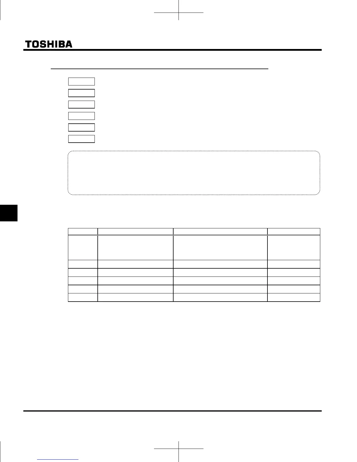
[Parameter setting]
Title Function Adjustment range Default setting
Analog/logic input selection
(VI terminal)
0: Voltage signal input (0 - 10V)
1: Current signal input (4 - 20mA)
2: Logic input
3: Voltage signal input (0 - 5V)
0
VI point 1 setting 0 - 100(%) 0
VI point 1 frequency 0.0 - 400.0 (Hz) 0.0
VI point 2 setting 0 - 100(%) 100
VI point 2 frequency 0.0 - 400.0 (Hz) *
Analog input filter 4 - 1000 (ms) 64
* Default setting values vary depending on the setup menu setting. Refer to section 11.5.
Note 1: Do not set point 1 and 2 ( and ) to the same value. If they are set to the same value,
is displayed.

 Loading...


