E6581595
A-14
1
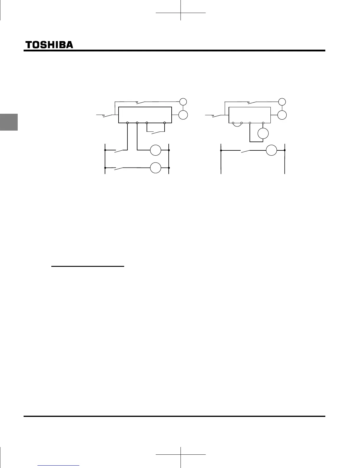
Motors with a brake
When motors with a brake are directly connected to the inverter's output, the brake cannot be released
at startup because of low voltage. Wire the brake circuit separately from the main circuit.
Circuit diagram 1 Circuit diagram 2
MC3
MC2
MC1
MC2
B
IM
MC3
MC1
MC3
FLB FLC S2 (ST) CC
3-phase
power
source
MC2
RY
3-phase
power
source
MC1
MC2
B
P24
OUT
IM
RY
+
–
NO CC
In circuit diagram 1, the brake is turned on and off through MC2 and MC3. If you do not wire it as shown
in diagram 1, an over-current trip may occur because of a bound current during brake operation.
(Example of running preparation ST assigned to terminal S2.)
In circuit diagram 2, the brake is turned on and off by using low-speed signal OUT. (Refer to section
6.1.1)
In some situations, such as with elevators, turning the brake on and off with a low-speed signal may be
appropriate. Be sure to contact us before designing your system.
1.4.2 Inverters
Protecting inverters from overcurrent
The inverter has an overcurrent protection function. The programmed current level is set to the
inverter's maximum applicable motor. If the motor used has a small capacity, the overcurrent level and
the electronic thermal protection must be readjusted. If adjustment is necessary, refer to section 3.5,
and make adjustments as directed.
Inverter capacity
Do not use a small-capacity (kVA) inverter to control the operation of a large-capacity motor (two-class
or more larger motor), no matter how light the load is. Current ripple will raise the output peak current
making it easier to set off the overcurrent trip.

 Loading...


