140
5. Using soft jaws, secure the gear case into a vise.
Using a propane torch, heat the gear case to approxi-
mately 200° F (93° C); then carefully install the pin-
ion gear assembly into the case. Install the lock
collar to secure the pinion into the case. Using the
Pinion Gear Lock Collar Socket, tighten to 125 ft-lb
(169.5 N-m).
PK252
PK251
6. Allow the gear case to cool; then lightly grease and
install a new pinion shaft seal. If Backlash and Gear
Tooth Contact are within specification, proceed to
step 7.
PK247
Checking Backlash
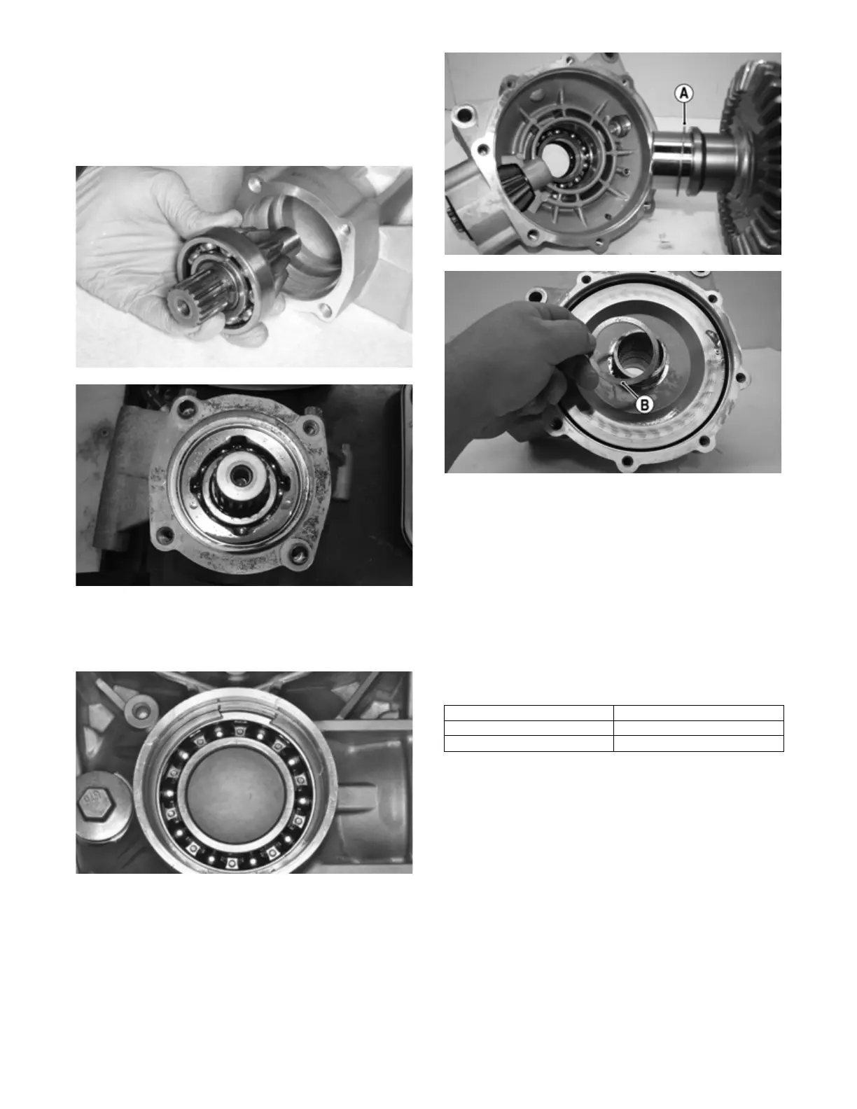
A. Place the original case side shim (A) onto the ring
gear housing; then place the ring gear into the gear
case. Place the cover side shim (B) onto the ring gear
housing; then temporarily install and secure the
cover to the gear case.
PK262A
PK249A
B. While holding the pinion gear shaft, place a horizon-
tal type dial gauge through the filler hole and against
the ring gear. Rotate the pinion gear shaft back and
forth; then record the reading from the dial gauge.
Check at three different locations spaced around the
ring gear. Standard specification is 0.05-0.25 mm
(0.002-0.010 in.).
C. If the measurement is out of adjustment, the shims
must be replaced. Refer to the included chart for
instructions regarding replacement of the case side
(right side) shims. If the case side shims are replaced,
the cover side shims must also be replaced to com-
pensate for the backlash adjustment.
Gear Tooth Contact
A. After backlash has been set, the gear tooth contact
must be confirmed.
B. Remove the ring gear housing. Thoroughly clean the
gear teeth of the ring and pinion gears. Apply
machinist’s dye to several teeth of the pinion gear.
Temporarily install the ring gear housing with shims
used when setting backlash. Install the cover.
C. Rotate the pinion gear shaft back and forth, so the
dye-coated gear teeth contact each other.
D. The dye should show that the contact area of the two
sets of teeth are centered. If contact is too high or too
low on the teeth, the pinion gear shaft shim must be
exchanged to achieve proper tooth contact while
maintaining correct backlash.
Backlash Right Shim Adjustment
Under 0.05 mm (0.0020 in.) Increase shim thickness
Over 0.25 mm (0.010 in.) Decrease shim thickness