B
86
Repair and Service Manual
REAR AXLE AND SUSPENSION
Read all of SAFETY and this section before attempting any procedure. Pay particular attention to Notices, Cautions, Warnings and Dangers.
10002660
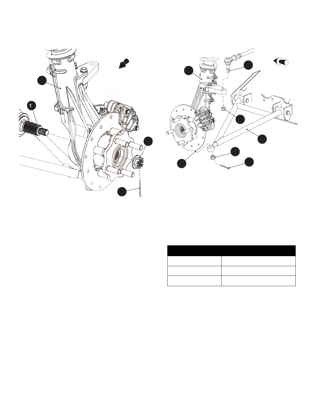
Fig. 2 CV Axle Attachment
7. Remove the cotter pin (22) and castellated nut (23)
attaching the lower ball joint to the control arm (20)
(Ref. Fig. 3).
8. Loosen, but do not completely remove, the lock nut
(24) connecting the outer tie rod end (21) to the strut
assembly (13).
9. Free the outer tie rod end (21) by tapping upward
using a rubber mallet.
10. Remove the lock nut (24)from the outer tie rod end
(21).
11. Remove the cotter pin (22) and castellated nut (23)
securing the control arm (20) to the lower ball joint
(25).
12. Separate the lower ball joint (25) from the lower con-
trol arm (20) using a ball joint separator (Ref. Fig. 3).
13. Remove the axle (10) from the strut assembly (13)
by pulling the strut assembly outward (Ref. Fig. 2).
14. Remove the CV Axle from the differential using a pry
bar.
Fig. 3 Control Arm and Tie Rod End Attachment
Assemble in the reverse order of removal using new lock
nuts and cotter pins.
Apply commercially available anti-seize compound to the
axle end prior to installation.
Tighten all hardware to the torque values specified below.
Continue tightening castellated nuts until the cotter pin
can be installed.
Differential Removal
Tool List Qty.
Wrench, 9/16” ..............................................................1
Socket, 9/16”................................................................1
Ratchet ........................................................................1
Lifting Device ...............................................................1
Torque Wrench, ft, lbs. .................................................1
Thread Locking Compound, Red.................................1
1. Remove the flip seat (See Rear Seat Removal and
Installation on page 75).
2. Remove both CV Axles (See Rear CV Axle Removal
on page 85).
Item Torque Specification
25 12 - 14 ft. lbs. (16 - 19 Nm)
24 45 - 55 ft. lbs. (61 - 74 Nm)
16 100 - 110 ft. lbs. (136 - 149 Nm)
Front of Vehicle