B
ELECTRICAL
Read all of SAFETY and this section before attempting any procedure. Pay particular attention to Notices, Cautions, Warnings and Dangers.
49
Repair and Service Manual
10002660
ELECTRONIC SPEED CONTROL
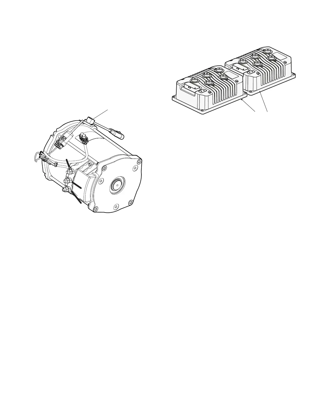
Speed Sensor
The speed sensor uses a sealed sensor to read the
impulses of a ring magnet that is attached to the armature
shaft of the motor speed sensor (Ref. Fig. 8). Magnetic
pulses change to electrical signals, which the controller
uses to determine the motor speed.
Test the speed sensor and replace if necessary (See
FAULT TESTING on page 52).
Fig. 8 Speed Sensor
Rotary Position Sensor
The rotary position sensor determines the speed of the
vehicle. The rotary position sensor is connected through
the main harness to the electronic speed control system.
With no pressure applied on the accelerator pedal, the
rotary position sensor remains in the neutral position.
When the pedal is pressed, the amount of deflection in
the rotary sensor is transferred to the electronic speed
control system. The speed control system controls the
speed of the motor that transmits power to the electric
powertrain module in the vehicle.
Controller
The controller is a solid state unit that activates a sole-
noid, and controls the function of the vehicle by respond-
ing to inputs from the rotary position sensor, motor speed
sensor and many other units. The controller is located
under the flip seat at the rear of the vehicle (Ref. Fig. 9).
Fig. 9 Controllers
The main wire harness, rotary position sensor, and speed
sensor are connected to the controller with a 24-pin plug.
The rotary position sensor is connected to the controller
with a 2-pin plug on the main wire harness. The speed
sensor is connected to the controller with a 3-pin plug on
the main wire harness.
The controller is connected to the batteries and creates a
regulated power supply for the rotary position sensor.
When the pedal is pressed, the amount of deflection in
the rotary sensor changes the voltage which is fed back
to the controller. The controller senses the change in volt-
age and supplies the appropriate power to the motor.
The rotary position sensor unit and the controller are both
solid state units that contain no serviceable parts. The
testing procedures test the basic functionality of the
power and control wiring systems. Once the functionality
of the wiring has been confirmed, the remaining tests are
used to identify which of the components (controller or
rotary position sensor) must be replaced.